AC Motors & Gear Motors > Technology > AC Motor Fundamentals
AC Motor Fundamentals
1. Overview of AC Motors
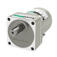
AC motors are electric motors that rotate by using power from a commercial AC power supply. They are easy to handle and have features that can be configured at a low cost. They are widely used to power various devices.
1.1 Easy to Use, Low Cost
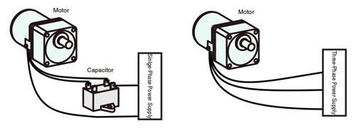
Easily operate AC motors by connecting the motor to an AC power supply. Low cost start-up is possible. For a single-phase motor, connect the capacitor between the power supply and the motor.
1.2 Structure of an AC Motor
The following figure shows the construction of a standard AC motor.
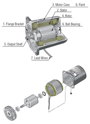
1. Flange bracket die cast aluminum bracket with a machined finish, press-fitted into the motor case
2. Stator comprised of a stator core made from electromagnetic steel plates, a polyester-coated copper coil, and insulation film
3. Motor case made from die cast aluminum with a machined finish inside
4. Rotor electromagnetic steel plates with die cast aluminum
5. Output shaft available in round shaft type and pinion shaft type. The metal used in the shaft is S45C. Round shaft type has a shaft flat (output power of 25 W 1/30 HP or more), while pinion shaft type undergoes precision gear finishing.
6. Ball bearing
7. Lead wires with heat-resistant polyethylene coating
8. Paint baked finish of acrylic resin or melamine resin
1.3 Operating Principle of AC Motors 1 (Arago’s Disk)
AC motors generate "magnetic flux" and "induced current" inside the motor by the actions of the stator and the rotor, and obtain rotational force.
The operation principle of AC motors can be explained by using Arago's disk.
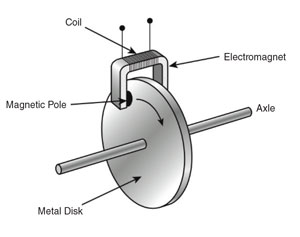
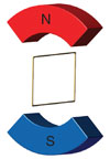
Arago’s disk is the phenomenon when a magnet is moved along the surface of a metal disk, the disk rotates to follow the magnet. First, prepare a round copper plate that can rotate freely and a magnet. Place them so that the copper plate is in between the magnetic poles but the magnet does not touch the copper plate.
Next, move the U-shaped magnet along the edge of the copper plate. The copper plate will start to rotate and chase the magnet.
Principle of Arago’s Disk
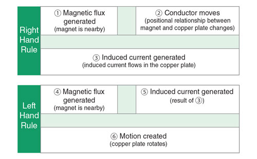
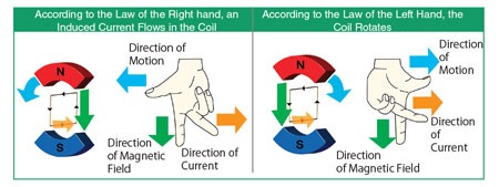
The principle of Arago's disk can be explained by "Fleming's Right Hand Rule" and "Fleming's Left Hand Rule".
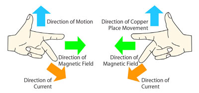
Fleming's Right Hand Rule indicates the direction of induced current (for generators) when a conductor is passed through lines of magnetic flux.
Fleming's Left Hand Rule indicates the direction of electromotive force (for motors) when a conductor is passed through lines of magnetic flux.
We apply these two laws to the relationship between the copper plate and the magnet in the order of the right hand rule, then the left hand rule.
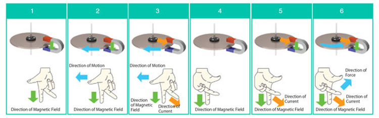
The rotation speed of the copper disk will be slightly slower than that of the magnet. This allows a rotation force to be generated by the conductor passing through the magnetic field.
1.4 Operating Principle of AC Motors 2 (Rotating Magnetic Field)
Replacing Arago Disks with Stators and Rotors
The operating principle of an AC motor can be explained by replacing Arago's disk with the internal structure of the AC motor. The N pole and S pole electromagnets are a simplified model of the stator. The closed coil in the center is a simplified model of the conducting rotor.
Place the closed coil in the magnetic field and rotate the outer magnet clockwise. Then, an induced current flows in the coil. When current flows, it reacts with the magnetic field and generates an electromotive force in the coil. The coil starts to rotate in the same direction as the magnet.
In an actual motor, the rotor is like a series of overlapping coils connected together so the rotational force can be generated efficiently.
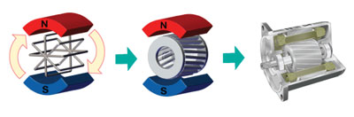
A squirrel cage rotor is a rotor with multiple skewed aluminum and iron bars. In a squirrel cage rotor, current flows in the aluminum part.
Rotating Magnetic Field (Single Phase Power Supply, Three Phase Power Supply)
As the stator generates a rotating magnetic field around the rotor, the rotor rotates.
The next section explains how the AC motor generates a rotating magnetic field.
Single Phase Power Supply - Phase Shift using Capacitor
Inside a single-phase motor, there are two windings: the main winding and the auxiliary winding.
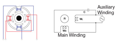
Connect the main winding to the power supply and the auxiliary winding to the power supply via the capacitor.
Current from the power supply flows directly to the main winding. On the other hand, the current through the capacitor flows through the auxiliary winding.
When operating with a single-phase power supply, we use a phase advancing capacitor to generate a waveform close to a two-phase power supply and generate a rotating magnetic field.
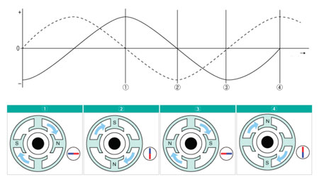
When connecting a single-phase power supply, repeat the phenomena ① to ④.
①Voltage is applied to the main winding, voltage is not applied to the auxiliary winding. An N pole and an S pole are generated in the magnetic pole of the main winding.
②Voltage is applied to the auxiliary winding, and voltage is not applied to the main winding. An N pole and an S pole are generated in the magnetic pole of the auxiliary winding.
③Voltage is applied to the main winding, voltage is not applied to the auxiliary winding. A magnetic pole opposite to that in ① is generated in the magnetic pole of the main winding.
④Voltage is applied to the auxiliary winding, and voltage is not applied to the main winding. A magnetic pole opposite to that in ② is generated in the magnetic poles of the auxiliary winding.
In this way, the magnetic field generated in the stator changes to produce clock-wise rotation.
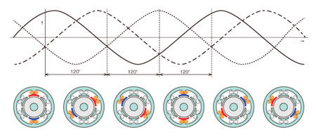
For Three-Phase Power Supply - Phase Shift of Power Supply
In single-phase motors, there are two windings, the main winding and the auxiliary winding, but three-phase motors consist of three windings.
Assuming U, V, W phases on the power supply side, there are three paths that the current can flow, UV, VW, WU. Connect these windings directly to the power supply.
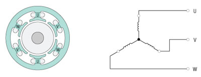
In the U, V, W line of the three-phase power supply, each phase is shifted by 120 °. Since this phase shift creates a rotating magnetic field in the stator, it is unnecessary to connect a capacitor, such as with a single-phase motor.
1.5 Types of AC Motors
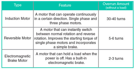
Induction Motor
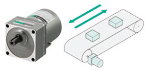
Induction motors are ideal for applications that operate continuously in one direction.
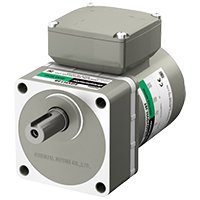
Reversible Motor
Reversible motors are ideal for applications where bidirectional operation is repeated frequently.
By incorporating a simple brake and increasing the starting torque, it is possible to switch the direction of motor rotation instantaneously.
• Structure of Simple Brake
Reversible motors incorporate a simple brake mechanism (friction brake) at the rear of the motor.
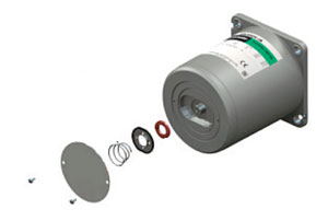
The brake mechanism constantly applies pressure to the brake shoe, which rubs against the brake disk. Once the motor stops, overrun can be significantly reduced compared to an induction motor.
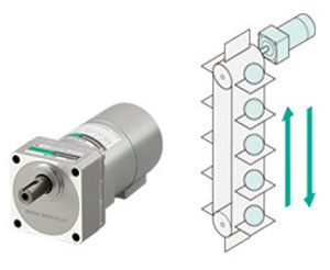
Electromagnetic Brake Motor
Electromagnetic brake motors are ideal for applications requiring load holding, such as vertical drive.
By incorporating a non-excitation type electromagnetic brake, it is possible to hold the load when the power is turned off.
Electromagnetic brakes are available with induction motors and reversible motors.
Single-Phase AC Gear Motors
Three-Phase AC Gear Motors
Reversible AC Gear Motors