Temperature Rise and Life of an AC Motor
1. Temperature Rise and Heat Resistant Class of AC Motor
Electrical Energy Conversion and Loss
An AC motor is an energy conversion device that converts input electrical energy into power for rotation and outputs it. Electrical energy is not 100% converted to power, and some energy is lost (heat).
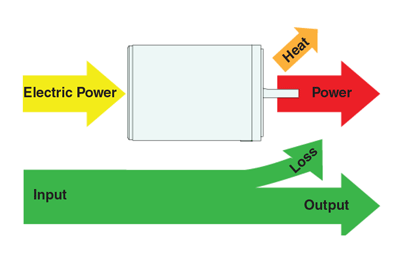
Motor temperature rise affects the operating time limit and motor life.
Motor heat class and burnout
The heat resistant class is a classification based on the heat resistant grade of the insulating material. It is defined by JIS standard. Our AC motors are classified as either Class E (120° C) or Class B (130° C). Classification varies from series to series.

If the internal temperature of the motor exceeds the heat class value for a while, the winding film melts and shorts. This phenomenon is called burnout. The burnt out motor will stop working. Also, if not burned, the temperature rise affects the motor life. During operation, be careful not to exceed the winding allowable temperature.
As the winding temperature inside the motor can not be measured directly, measure the surface temperature of the motor case as a reference.
For our AC motor, the temperature difference between the windings and the motor case is up to 30 ° C. The guidelines for each heat resistant class are summarized in the table below.

Our AC motors will not burn out if the motor case temperature is below 90° C.
2. Operating Rated Time of AC Motor
We will introduce the temperature rise of the motor winding when actually driving the motor.
Motor winding temperature change due to the passage of operating time
We have specified the temperature rise and time rating of the AC motor under the severest conditions for the motor.
• Measurement condition:
・ Ambient temperature: 50° C (The upper limit of motor specification. It varies according to the product). No load for single phase motor, rated load for three phase motor
・ Load condition: No external forced cooling (no air flow or cooling by an external fan). Motor alone (there is no gear head or heat sink)
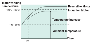
The 120° C (130° C) on the vertical axis of the graph is the heat resistant class line of Class E (Class B). Indicates the allowable winding temperature of the motor.
• Induction motor: "continuous rating" In the case of an induction motor, regardless of the passage of time, it saturates below the allowable winding temperature. Even if it runs continuously, there is no concern about burnout. Therefore, induction motors are "continuously rated".
• Reversible motor: "30 minutes rated" In the case of a reversible motor, the allowable winding temperature is reached around 30 minutes. Therefore, reversible motors are "30 minutes rated". However, the rated time is just a guide. The degree of temperature rise changes depending on the ambient environment. This measurement condition is specified under the condition that the heat generation is the largest under the use condition of the motor. When using a motor, judge based on the surface temperature of the motor case is 9° C or less.
The causes of high motor temperature
If you are concerned about the temperature rise of the motor, please review the ambient environment. The following are examples of the causes of the high temperature of the motor:
・ Ambient temperature is high
・ Motor shaft is restrained
・ The voltage is high
・ Voltage drop is large
・ Capacitor capacity is greater than rated
・ Frequent start and stop (including braking by brake pack)
Changing the conditions, such as lowering the ambient temperature, may reduce the temperature rise.
3. AC Motor Burnout Protection Function
If the temperature rise of the AC motor exceeds the allowable winding temperature, it may burn or affect the life. Therefore, some AC motors have built-in overheat protection devices for burnout protection. The presence or absence of the function can be checked on the motor specification table or name plate.
Thermal protector (TP)
A thermal protector is a feature that shuts off the input to the motor before it reaches the allowable winding temperature. It senses the winding temperature inside the motor and opens the contact point of the power line and stops the motor if it exceeds a certain temperature.
When the winding temperature inside the motor drops below a certain temperature, it will automatically recover and resume operation.
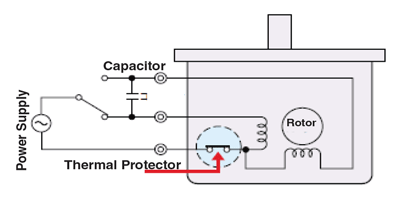
With our AC motors, the ones marked “THERMALLY PROTECTED” or “TP” on the specification table or nameplate are equipped with an automatic reset type thermal protector. It is built into some motors with mounting angle dimensions of 70mm to 104mm.
Operation image of automatic reset type thermal protector
The automatic reset type thermal protector automatically turns on / off the contact depending on the temperature. The figure below is an example of the operation of the thermal protector.
Open: 130 ° C ± 5 ° C
Close: 82 ° C ± 5 ° C
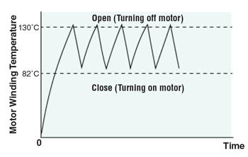
The specification of operating temperature differs depending on the installed product. In addition, the motor winding temperature when the thermal protector operates is slightly higher than the above operating temperature. When the thermal protector is open, the motor may seem to stop but it may return automatically and start moving suddenly. For safety, turn off the motor before work with personnel touching the device for inspections.
Impedance protection (ZP)
Impedance protection is a function that increases the impedance (resistance) of the motor's winding and can reduce the increase in input even if the motor is constrained. The impedance protection motor is designed so that the temperature rise does not reach the allowable winding temperature.
In our AC motors, those marked "IMPEDANCE PROTECTED" or "ZP" on the specification table or nameplate are impedance protected motors. This applies to some motors with a mounting angle of 60 mm or less.
4. Operating Cycle and Temperature Rise
Temperature rise of a motor is affected by operating conditions. We will explain the temperature rise and the limitation of the operation condition of intermittent operation of reversible motor and intermittent operation using brake pack.
Intermittent operation and temperature rise of reversible motor
When a reversible motor is used intermittently for a short time, a large current flows when the motor starts up or reverses, and heat generation increases. On the other hand, when the motor stop time is long, the natural cooling effect is large, so the temperature rise can be suppressed.
• Reversible motor operation cycle and temperature rise
The temperature rise of our reversible motor is compared under conditions of multiple driving cycles. The measurement assumes the most severe condition in motor specification. Also, a heat sink is attached to the motor. (Size: 165 x 165 mm, thickness: 5 mm, material: aluminum).
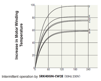
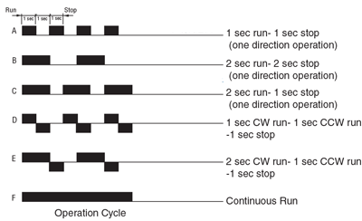
As in condition A and condition B, setting the stop time equal to the operation time can suppress the temperature rise of the motor. As in the condition C to condition F, the shorter the stop time, the larger the temperature rise.
• Heat sink type and temperature rise
The temperature rise can be suppressed by reviewing how to install the motor. In particular, the size and material of the heat sink to be attached changes the temperature rise of the motor as shown below.
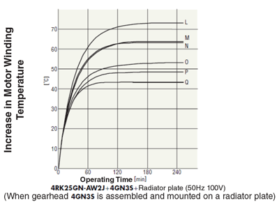
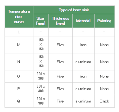
If the size of the heat sink is increased like L · O or N · P, the temperature rise can be suppressed. Heat dissipation is enhanced by using aluminum, which has a higher thermal conductivity than iron, such as M, N, O, and P, and the motor temperature can be reduced.
If aluminum is painted black, as with P and Q, the temperature rise can be suppressed.
Intermittent operation and temperature rise by brake pack
In the operation principle of the brake pack, it was explained that a large braking current flows when the brake pack is stopped momentarily. If motor operation / braking is repeated in a short time, the temperature rise of the motor and brake pack will be large, and the continuous use time will be limited. The operation / braking repeated cycle with a brake pack should be as follows.
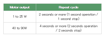
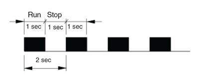
Depending on the drive conditions, the temperature rise of the motor will be large. Use it so that the surface temperature of the motor case is 90 ° C or less.
5. Life of AC Motor
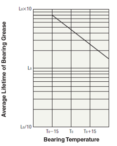
The life of the AC motor is based on the grease life of the bearing. If the grease degrades due to heat, the motor shaft will become difficult to rotate.
Average grease life of AC motor bearings
The following table shows the average bearing grease life time when using an AC motor under certain operating conditions.

Grease life is affected by temperature rise due to ambient temperature and operation cycle. Under the conditions in the above table, the bearing grease life is halved as the bearing temperature rises by 15 ° C. In contrast, the lower the temperature, the longer the life.
Life of motor with electromagnetic brake
In the case of a motor with an electromagnetic brake, in addition to the bearing grease life, the life of the electromagnetic brake is also considered. If the electromagnetic brake is damaged, you can not replace the electromagnetic brake alone. Every motor needs to be replaced. When braking with allowable load inertia moment repeatedly with a motor with electromagnetic brake, the lifetime of the electromagnetic brake is 2 million times. Combined use of a brake pack can extend the life of the electromagnetic brake.
6. Life of Gearhead
The life of the gearhead is based on the mechanical life of the bearing. The mechanical life is determined by the load applied to the bearing and the rotational speed.
Gearhead rated life
We define the rated life after defining certain operating conditions. The following table is an example.

*The operating conditions are common to all series and gearhead types.
Estimation of gear head life time
The life time in actual use is calculated by the following equation taking into consideration the operating speed, load amount, and load type. The smaller the load used for the permissible torque, the longer the life.
L1: gearhead rated life time value
K1: rotational speed coefficient. Calculated from the input rotation speed and the input rotation speed actually used.
K2: a load factor. It is obtained from the allowable torque of each gearhead and the torque actually used. When a large load is applied only at start and stop, as in the case of driving an inertial body, the average torque is taken as the working torque.
f: Ia factor (service factor) that changes depending on the type of load. Please see the table below for details.

* ・In this estimation of the life time, the values of radial load and axial load are also calculated in proportion to the load factor. Therefore, when the load factor is 50%, the radial and axial loads also have a 50% life. ・If the load factor is low and the radial load or axial load is large, the life time will be shorter than the one calculated by this formula.
