Brushless DC Motors > Technology > CS Gearbox Parallel Gear Mechanism
Development for Concentric Shaft Gearbox of Parallel Gear Reduction Mechanism
Oriental Motor's gearboxes, having a conventional parallel gear reduction mechanism, have a structure in which the output shaft of the gearbox (hereinafter referred to as gear output shaft) is offset from the center of the motor. The newly developed CS gearbox, however, has a parallel gear reduction mechanism, and also its gear output shaft is arranged to be concentric with the center of the motor. This makes it easier to design equipment such as a motor mounting plate. In addition, due to design innovation, the allowable torque and the permissible radial load have been significantly improved compared to conventional models. The CS gearbox is added to the line-up for the PKP Series 2-phase stepper motors and the BLH Series connector type brushless motors. The following describes the structure and features of the CS gearbox.
1. Introduction
In the 1950s, when foot mounting type motors were the mainstream, Oriental Motor released easy-to-use flange mounting type motors. In 1951, we launched the H Series and promoted “standardization” of compact AC motors which frame size and mounting pitch were unified for each output power (see Figure 1). At the same time, in order to take advantages of the flange mounting type motors, we developed the dedicated parallel shaft gearboxes using a parallel gear reduction mechanism.
It is easy and common to interchange Oriental Motor's gearboxes to that with a different gear ratio since the frame size and the mounting pitch are compatible even in different gear ratios (see Figure 2).
Afterward, Oriental Motor has evolved our motors into compact and high power motors. In accordance with evolution of motors, we have made efforts to improve the performances of parallel shaft gearboxes in terms of high torque, high strength, long life, and low noise.
The conventional parallel shaft gearboxes have a structure in which the gear output shaft is off set from the motor output shaft.
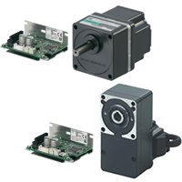
To meet the market request, we have developed a concentric shaft gearbox (CS gearbox), which is a parallel shaft gearbox and also has a concentric structure of the motor output shaft and the gear output shaft (see Figures 3 and 4). The following describes the structure and features of the CS gearbox.
2.Parallel Shaft Gearboxes
2.1 Structure
Figure 5 shows the structure of a parallel shaft gearbox of a parallel gear reduction mechanism. The gear output shaft of parallel shaft gearboxes is arranged avoiding the motor output shaft. Therefore, a structure in which the gear output shaft is off set from the center is commonly used. Arranging as large a gear as possible in the output stage enables to obtain a high allowable torque and design gearboxes with various gear ratios. The off set amount should be carefully considered because it is closely related to the gear design (see Figure 6).
Oriental Motor offers a wide range of products, including the GFS and GFV gearboxes for brushless motors, the GN and GV gearboxes for AC motors, and the SH geared type for the PKP Series 2-phase stepper motors.
To keep the design compact and light, Oriental Motor uses a machined pinion shaft on the motor to mate directly to the 1st stage wheel gear in the gearbox. Other manufacturers' motors may use a coupling to connect a round shaft from the motor to the gearbox, which increases its size and weight. By removing the coupling, common issues associated with couplings, such as backlash and slip, are also eliminated.
2.2 Installing to Equipment
When conventional parallel shaft gearboxes are installed to equipment, it is necessary to design the mounting plate while considering the off set amount of the gear output shaft relative to the center of the rotating shaft of the equipment side since the gear output shaft is off set from the center of the mounting surface of the gearbox (see Figure 7). On the other hand, a concentric shaft gearbox, where the output shaft is positioned at the center of the mounting surface of the gearbox, allows the mounting plate to design at the center of the rotating shaft of the equipment side, making it easier to design the equipment.
3. Concentric Shaft Gearboxes
3.1 Planetary Gear Reduction Mechanism
A planetary gear reduction mechanism is a typical mechanism of concentric shaft gearboxes. This mechanism features allowable torque can be significantly increased compared to parallel shaft gearboxes because the torque is dispersed in multiple planetary gears. In the line-up of Oriental Motor products, concentric shaft gearboxes of a planetary gear reduction mechanism are used for the PS geared type (see Figure 8) and the PN geared type.
A planetary gear reduction mechanism requires high precision annulus gear machining and multiple bearings to hold planetary gears. Therefore, the manufacturing manhours
and the number of parts are considerably increased compared to gearboxes of a parallel gear reduction mechanism. In addition, since the gear specifications of the motor output shaft (sun gear) must be changed for each gear ratio, a dedicated motor is required for each gear ratio (see Figure 9).
3.2 Development of CS Gearbox
3.2.1 Renewal of Structure for Parallel Shaft Gearbox
With regard to the CS gearbox development, we have examined a structure that a concentric shaft gear box can be achieved while inheriting the structure of the conventional parallel shaft gearboxes.
The conventional parallel shaft gearboxes were basically designed so that the outer shape of the gearbox would fit within the projection plane of the motor frame size. If both this design constraint and a concentric structure are tried to satisfy, the center distance between the motor output shaft and the first stage wheel gear is restricted. This makes the center distance of each gear pair be short, and as the result, the output stage wheel gear will be a small diameter. Therefore, it is difficult to design gear ratios exceeding 10 or transmit a large torque. To overcome this matter, it is necessary to increase the center distance of gear pair and enlarge the diameter of the output stage wheel gear (see Figure 10).
In the development of the CS gearbox, having a bulge on the gear case to arrange the first stage wheel gear in the bulged space while maintaining the mounting hole pitch, we secured the center distance. (See Figures 11 and 12.) As a result, we could enlarge the diameter of the output stage wheel gear and design the gear ratios of up to 20, enabling to transmit a large torque.
3.2.2 Curved Shape of Gear Case
The bulge of the gear case was made with a special curved shape that fits inside the circumscribed circle of the gear case, and was provided on the outlet side of the motor lead wires in order to minimize an impact on the surrounding area as much as possible (see Figure 13).
3.2.3 Improvement of Bearing Support Structure
If a concentric structure is applied to the parallel shaft gearbox based on the conventional design method, bearings of the gear output shaft must be supported by the gear case and the intermediate flange (see Figure 14). This structure causes the number of parts and the overall length of the gear case to increase. Therefore, for the CS gearbox, we adopted a structure in which bearings of the output shaft were supported by the gear case only, and the intermediate flange was eliminated (see Figure. 15). This reduced the number of parts and shortened the overall length of the gear case.
3.2.4 Improvement of Allowable Torque and Radial Load
In addition to enlargement of gears on the first and output stages, applying heat treatment to gears increased the allowable torque of the CS gearbox by approximately two times compared to the SH gearbox (see Figure 16).
Increasing the center distance of gear pair could also increase the size of bearings, which made the permissible radial load increase by up to four times compared to the SH gearbox. This enables appropriate tension control when heavy load transmission is required with the belt drive (see Figure 17).
3.2.5 Making Products Smaller and with Higher Torque
In the case of the conventional BLH Series brushless motors, the output power of the frame size 42 mm was 15 W and that of the frame size 60 mm was 30 W. This time, however, combining with the CS gearbox which allowable torque was improved, we added a new line-up of products that achieved the output power of up to 30 W despite its small frame size 42 mm (see Figure 18).
When the BLH Series conventional model of a 42 mm frame size (output power of 15 W) with a gear ratio of 10 is used, changing to the CS geared type with the same frame size (output power of 30 W) can drive a load up to twice the allowable torque of the conventional model if the same gear ratio is used. If a desired torque is the same, using the CS geared type of gear ratio 5 can increase by twice the rotation speed (see Figure 19).
The permissible radial load is also improved compared to the conventional model (see Figure 20). It contributes to downsizing and higher performance of equipment.
4. Summary
Re-evaluating the design constraint of conventional parallel shaft gearboxes, we have successfully commercialized concentric shaft gearboxes of a parallel gear reduction mechanism. We have also achieved improvements in the allowable torque and the permissible radial load for gearboxes by increasing the size of gears and bearings and applying heat treatment to gears. Although the motor output power is the same as the conventional models, making the motor size compact contributes to reduction in size and weight of equipment. We will continue to develop products that meet customer needs.
2-Phase Stepper Motors
DC Input Brushless Motors