The Structure and Positioning Accuracy of the DR Series Compact Electric Cylinder
Oriental Motor’s DR Series electric cylinders combine a motor and ball screw into an integrated assembly to create a compact and highly accurate positioning device. Unlike conventional cylinders, the DR Series features a new guide form that can be adapted to suit different load shapes and masses. It also features a large lead ball screw, which results in greater speeds and faster positioning. Furthermore, the DR Series can be mounted from multiple directions, thereby increasing the number of potential locations for installation, and contributing to more compact equipment. This report explains the structure, features and positioning accuracy of a 28 mm DR Series electric cylinder.
1. Introduction
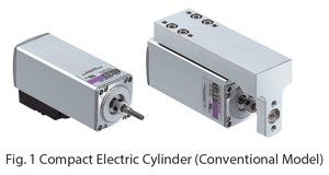
For applications that require accurate positioning, generally a stepper or servo motor is used. Compact electric cylinders are a type of linear actuator that combine a stepper motor and a ball screw into a single assembly (See Fig.1). Linear actuators require a guide for linear motion. Until now, there has only been one type of guide, and the applications it could be used for have been limited. Essentially, it could only be used with a rod type actuator without a guide, and the design required the use of an external guide mechanism. As such, guides could only be mounted from one direction, and there was demand for multi-directional mounting.
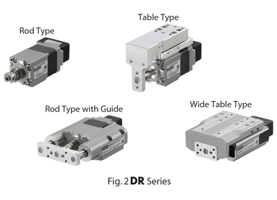
Now, with the newly developed DR Series, the number of guide types and mounting directions has been increased to allow for support of a variety of application (See Fig.2).
2. Compact Electric Cylinders
Compact electric cylinders feature a hollow rotor with directly incorporate ball screw and nut without the use of a coupling. Furthermore, they employ large diameter ball bearings that are placed around the periphery of the ball screw nut in order to shorten the total length of the device (See Fig. 3).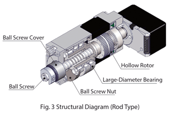
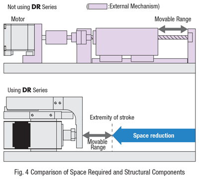
The structures of conventional actuators and the DR Series cylinder are compared in Fig. 4. Compact electric cylinders can reduce space requirements and with fewer parts, they also require less assembly time.
3. DR Series
3.1 Overview
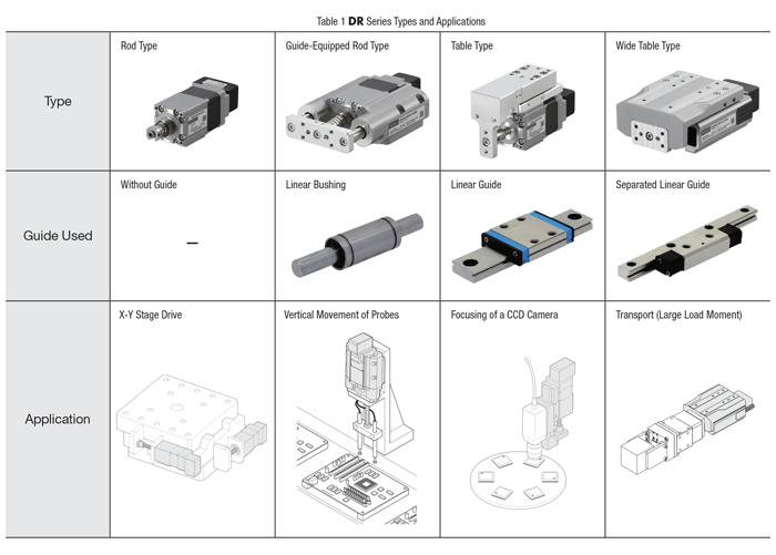
The DR Series is available in four models, the basic model being the guide-less rod type. In addition, there is the conventional guide-equipped table type, the guide-equipped rod type and the wide table type. This makes it possible to select a guide format that is suited for the intended application. For example, the guide-equipped rod type is best suited for low load moment/light load transport and push motion operation, while the wide table type is best suited for applications with large load moment applications (See Table 1).
There are two types of motors to choose from: the AZ Series (or “AZ Motor”), which comes equipped with a batteryless, mechanical multi-revolution absolute sensor (ABZO sensor), or a PKP stepper motor. The basic structure of the newly developed guide-equipped rod type and wide table type cylinder will now be explained.
3.2 Structure
3.2.1. Guide-Equipped Rod Type
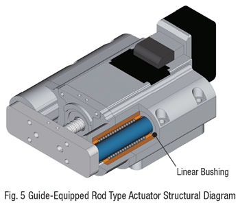
A structural diagram for a guide-equipped rod type cylinder is shown in Fig. 5.
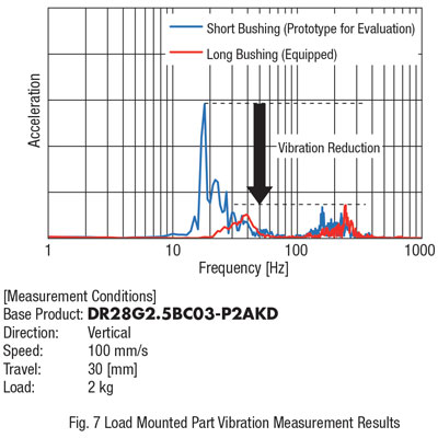
The guide-equipped rod type cylinder utilizes a long, rigid bushing. Use of the long rigid bushing reduces vibrations made by the vibration of the ball screw shaft.
In order to increase rigidity, the bushing has been placed near the load mounting plate.
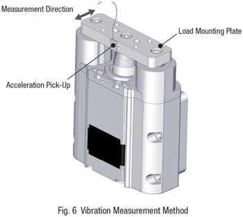
An acceleration pick-up was placed on the moving part, and ran the motor with bushing of different lengths. Then an FFT analyzer was used to analyze the frequency. The results of this analysis are presented in Fig. 6 and 7. After comparing long and short bushings, we learned that there was a reduction in vibration. The vibration peaks were cyclical, and caused by the vibration of the ball screw shaft.
3.2.2. Wide Table Type
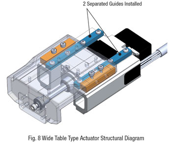
Wide table type cylinders have been designed to offer increased rigidity and reduced height from the installation surface. Normally, in order to increase rigidity, a large guide would be used and it would be necessary to place it above the motor, making the product larger. Because wide table type cylinders use two separated guides, the distance between the guide rails is increased (See Fig. 8).
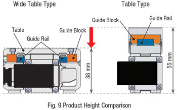
The difference in height between wide type and conventional table type cylinders is compared in Fig. 9. Wide table type cylinders uses a guide that are mounted the external side of the motor. This makes the product shorter while increasing rigidity. As the separated guide has been designed to increase rigidity, the preload must be appropriately adjusted at the time of assembly. The guide blocks add force from the external side to adjust the preload. If the preload is small, rigidity decreases, causing increased displacement in the ends of the moving components, ultimately causing a decreased service life due to the deflective load on the ball screw. If the preload is large, rigidity will increase, but the guide’s sliding resistance value will also increase, and cause a decrease in thrust. This relationship is used to determine the appropriate preload applied by the wide table type to the guide.
3.3 Permissible Moment
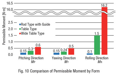
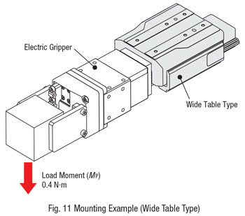
As mentioned above, the DR Series offers three guide types, each with a different degree of rigidity. The permissible moment for each guide form is shown in Fig. 10. The guide-equipped rod type is the smallest, followed by the table type and the wide table type. Fig. 11 shows a mounting example using an electric gripper. The pitching direction load moment is 0.4 N·m, which exceeds the permissible moment of 0.3 N·m for the table type, but that is less than the permissible load moment of 0.6 N·m for the wide table type, so that type can be used. Select a guide type that is suited for the load moment.
3.4. Displacement of Moving Parts
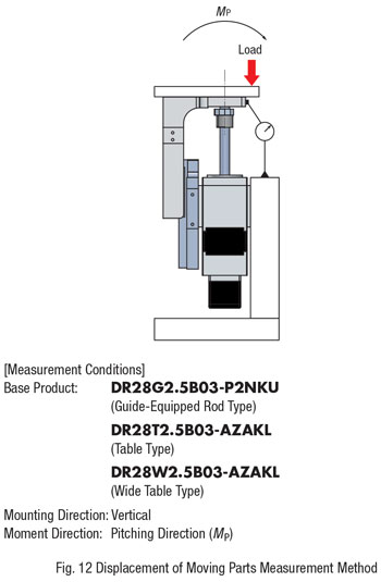
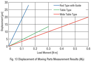
A method for measuring the displacement of moving parts in the pitching direction and its results are shown in Fig. 12 and 13. The displacement of moving parts refers to the displacement that occurs when a load is added. It is largest with simple guide-equipped rod type cylinders, and smallest with wide table type cylinders. The more rigid the guide is, the smaller the displacement of moving parts. This allows for accurate positioning even when the load is fluctuating.
3.5. Improved Freedom for Installation
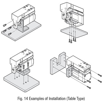
In comparison to conventional products, the DR Series electric cylinders offer more freedom and flexibility for installation (See Fig. 14 and 15).
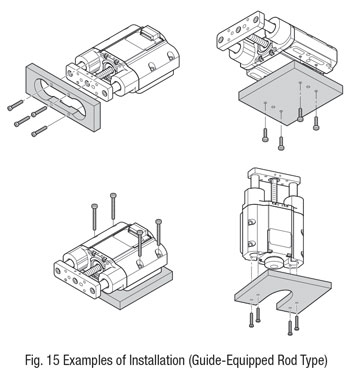
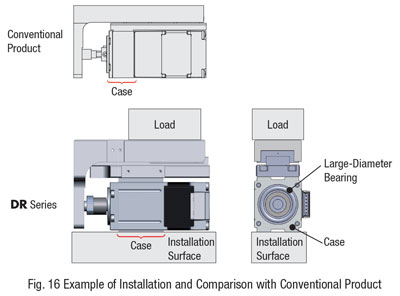
Depending on the mounting direction, the work load will cause the table type case to deform and the stress this applies to the large-diameter bearing may reduce the thrust and service life of the large-diameter bearing. With that in mind, the case has been designed to be longer and to reduce displacement so that the load is not concentrated (See Fig. 16).
4. Characteristics
4.1. Speed-Transportable Mass Characteristics
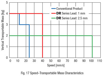
Due to customer demand the speed of our compact electric cylinders has been increased. In addition to a conventional 1 mm ball screw lead, the DR Series offers a 2.5 mm type that increases the maximum speed to 100 mm/s (See Fig. 17). With the 1 mm lead, the vertical transportable mass is 4 kg. In comparison to general actuators of the same size, the DR Series allows for the transportation of heavier loads.
4.2. Positioning Accuracy
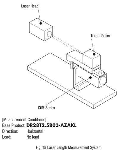
Similar to previous generation products, the DR Series electric cylinders are capable of highly accurate positioning. Next, we’ll introduce the measurement results for repetitive positioning accuracy and stepping accuracy, which are the basic characteristics of the series. The displacement measurements provided in this report were obtained using a laser length-measurement system as shown in Fig. 18.
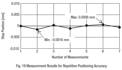
Repetitive positioning accuracy is calculated as 1/2 the maximum error amount of the stop position when positioning to an arbitrary point in the same direction. A ± sign is added to this value when it is displayed. Fig. 19 shows the measurement results for repetitive positioning accuracy. The actual value is ± 0.0011 mm, which is suitable for drive mechanisms that require a high-degree of accuracy. (The specification value is ± 0.003 mm at a constant temperature and load.)
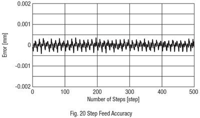
The maximum error between the theoretical and the actual feed when each pulse is sent is called “step feed accuracy”. Fig. 20 shows that the actual feed is within a range of ± 0.0004 mm. Because the step feed error is small, it is suitable for applications that require very small feed amounts, such as stage movement.
4.3. Vibration Characteristics
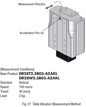
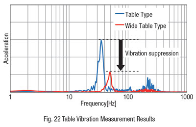
Wide table type actuators offer high rigidity, which makes the table less prone to vibration. A method for measuring table vibration is shown in Fig. 21, and a comparison of the table type and wide table type vibration characteristics is shown in Fig. 22. When the highly rigid wide table type actuator is used, the table is less prone to vibration, making it effective for applications in which table vibration could cause a negative effect, such as camera transport.
5. Temperature and its Effect on Positioning Accuracy
Warming and cooling operations are often performed on measuring devices and machine tools to suppress fluctuation due to thermal drift in circuit elements and the thermal expansion of mechanical components.
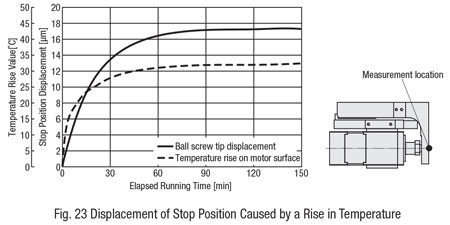
Similarly, with motors and actuators, temperature and its effect on positioning accuracy must be considered. One factor is that the temperature of mechanical components rises due to the heat from the motor, causing the stop position to fluctuate as a result of the thermal expansion of the mechanical components (See Fig. 23).
6. Adjusting the Running Current Using a Load Factor Monitor
As mentioned previously, changes in temperature effect positioning accuracy. If there is excess thrust, heat generation can be suppressed by reducing the running current. The DR Series AZ Motor allows for monitoring of the motor’s load factor, making it easy to optimize the running current. The motor load factor is a ratio of the actual load torque to output torque (thrust) at the running speed (See Fig. 24).
The AZ motor can easily monitor the motor load factor using the MEXE02 support software.
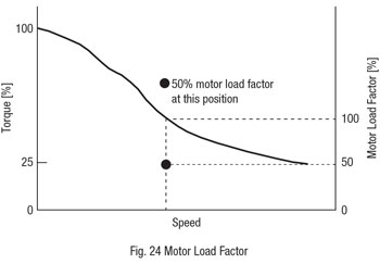
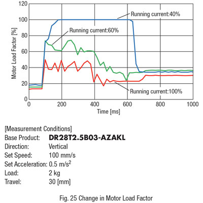
Fig. 25 shows the monitor wave forms of the motor load factor during trapezoidal drive. The three conditions for setting the running current are listed. Regarding the operating conditions, the load factor is 100% or more when Accuracy Warming and cooling operations are often performed on measuring devices and machine tools to suppress fluctuation due to thermal drift in circuit the running current is at 40%, and it is presumed that the motor will not run normally due to overloading.
Speed is shown in Fig. 26. At a running current of 40%, the motor does not run at the set speed, but when the running current is at 60%, it runs without any problems.
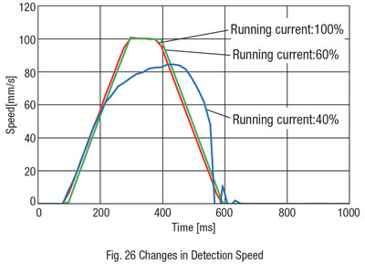
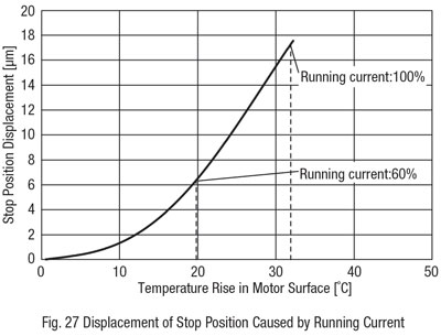
Fig. 27 shows the displacement of the stop position due to a rise in temperature resulting from changes in running current. The rise in temperature at the motor surface when the running current is at 100% is about 32°C, and the displacement of the stop position is about 17.5 μm. By lowering the running current to 60%, the rise in temperature at the motor surface is reduced to approximately 20°C, and the displacement of the stop position is about 6 μm.
The motor load factor monitor makes it possible to set the optimum current value, and the displacement of the stop position due to thermal expansion of the mechanism can be minimized.
7. Summary
Oriental Motor’s DR Series electric cylinders combine a stepper motor with a ball screw into an integrated assembly to achieve both a small size and a high degree of accuracy. It allows the selection of the form that best suits the application, and can be mounted from multiple directions, improving usability. Furthermore, through the use of the load factor monitor function, the AZ Series simplifies the optimization of the running current. This allows for the reduction of thermal expansion of mechanical components due to motor heat thus enabling more accurate positioning.
Moving forward, efforts will focus on the development of easy-to-use products that can reach optimal operation sought by customers.
