Network Products > Technology > MRC01 Controller Development
Development of Robot Controller MRC01 and Example for Introducing Robot to Equipment
Introduction of robots has been increasing for the purpose of labor savings through automation in equipment. However, since commercially available industrial robots have a restriction on size and also many of them are oversized, there is a growing demand for "in-house development of robots" in accordance with the size of equipment. Knowledge about robot control is required to control in-house developed robots, but difficulty in controlling a robot has been a large obstacle for introducing in-house developed robots. The robot controller MRC01 and the dedicated programming software MRC Studio were developed with the goal of making designing, testing and implementing in-house developed robots easy, even for first time equipment designers. This report introduces the technology and functions of the MRC01 controller and the MRC Studio software. It offers examples to reduce the start-up time of equipment and the create programs by introducing in-house developed robots to in-house equipment.
1. Introduction
The number of industrial robots sold worldwide has increased significantly in recent years. Especially in processes easy to automate such as handling and transferring devices, the introduction of robots is accelerating for the purpose of attaining labor-saving. In many countries around the world, automation using robots will continue to grow in the future in order to solve labor shortages caused by a decrease in the working-age population(1).
When introducing robots, it is common to use commercially available industrial robots. However, commercially available industrial robots are difficult to retrofit to existing equipment because they have a restriction on size and also many of them are large sized. For this reason, "in-house development of robots" has increased, and accordingly the demand of robot controllers that can control in-house developed robots has also increased.
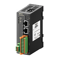
This report describes the technology and functions of the robot controller MRC01 and the dedicated programming software MRC Studio (see Figure 1), which were developed to meet the demand.
2. Technology Necessary for Robot Control
Typical industrial robots include vertical articulated robots and SCARA robots (see Figure 2). It is important to introduce the most suitable robot according to the application because each robot has different characteristics such as a movable range, speed, and accuracy. This chapter explains the technology required for controlling various types of robots.
2.1. Control of Robot
The position of the end-effetor where a robot actually performs a task is called “Tool Center Point” (hereinafter referred to as TCP). Robot control refers to the control of the entire robot that moves the position, speed, and trajectory of the TCP as desired, rather than the individual control of each motor that drives each joint of the robot. This is the basic role of the robot controller (see Figure 3).
2.2. Forward Kinematics and Inverse Kinematics
Kinematics calculation plays an important role in controlling a robot. It is coordinate transformation calculation that converses the position of the TCP and the angle of each joint for a robot. There are two types: “forward kinematics calculation” calculates the TCP position from each joint angle, and “inverse kinematics calculation”, calculates each joint angle from the TCP position. They have a relationship of inverse conversion with each other (see Figure 4). These calculations are essential for robot control, and the calculation method varies depending on the robot structure. The more complex the robot structure, the more sophisticated the kinematics calculation becomes.
In kinematics calculation, the Cartesian coordinate system (base coordinate system) representing the TCP position, the origin position of each joint, and the sign of the rotation direction are defined first. If the origin position and rotation direction of each joint deviate from this definition, the robot cannot be controlled properly. In addition, since kinematics calculation requires the specification information on various components such as the arm length, it is important to set the accurate specification information.
Also, depending on the robot structure, multiple postures (right-handed/left-handed system) may occur for a single TCP position. This means that there are multiple solutions in inverse kinematics calculation (see Figure 5). For some robots, if the posture changes, the joint section interferes with the surroundings or the movable range changes. Therefore, it is necessary to control the robot while selecting an appropriate posture according to the details of operation.
2.3. Singularity
Robots have an uncontrollable posture called a singularity that is caused by the robot structure (see Figure 6). Some joint speeds rapidly increase near the singularity (see Figure 7).
The posture to be a singularity can be obtained by the kinematics calculation of a robot. To control the robot safely, it is necessary to prevent a rapid increase in the joint speed near the singularity.
2.4. Trajectory Control
In control operation of the TCP trajectory, the angle and speed profiles of each joint can be calculated by performing inverse kinematics calculations of each point on the trajectory in the Cartesian coordinate system (see Figure 8).
The angle and speed profiles of each joint basically become complex profiles that change over time. So advanced motion control technology is essential for robot control in order synchronously to operate the motors used in each section according to the profiles.
3. Robot Controller MRC01
3.1. Structure of Controllable Robots
The MRC01 is a robot controller developed for controlling motors from the αSTEP AZ Series equipped with a batter-free absolute sensor(2). Inputting the structure and mechanism specification information of a robot to the MRC01 controller can operate the robot in a common method without considering its structure.
Offsets may occur depending on the structure of a robot, but the MRC01 controller performs kinematics calculation using a structural model that takes these off sets into account (see Figure 9). For this reason, even in the case of in-house development of robots with a high degree of freedom in structure, operation can be performed by setting appropriate mechanical specification information. The end effector axis can also be controlled.
3.2. System Configuration
The MRC01 controller is compatible with EtherNet/IPTM. Controlling I/O or sending operation data from a host controller over EtherNet/IPTM can easily achieve control of in-house developed robots. (3)
The MRC01 controller has direct I/O of 8 inputs and 8 outputs. Simply inputting signals can perform various types of control operation such as start/stop of operation and control of peripheral equipment.
3.3. Coordinate Systems Managed by MRC01
Selecting an appropriate coordinate system according to movements of a robot can intuitively perform teaching operation even for a robot with complicated structure. It is possible to create a wide variety of operation programs that maximize the degree of freedom of movements the robot has. The following describes coordinate systems and definitions that can be selected by teaching operation using the MRC01 controller.
1) Cartesian Coordinate System (XYZ) [Unit: mm]
A Cartesian coordinate system is most frequently used. There are two types: one is the "base coordinate system”, which fixes the origin position to the center of the base mounting surface of a robot, and the other is the “user coordinate system” which can change the origin position as desired (see Figure 11).
2) Hand Angle Coordinate System (RxRyRz) [Unit: deg]
This is a coordinate system to control the angle of the hand at the front end of the arm that can be set for vertical articulated and SCARA robots (see Figure 12). Regardless of the posture of a robot, it can achieve movements to keep the angle of the hand constant and to grasp a load from various angles.
3) Tool Coordinate System (TxTyTz) [Unit: mm]
This is a Cartesian coordinate system with the position of the hand of a robot as an origin (see Figure 13). The direction of each coordinate varies depending on the angle of the hand. It is possible to move forward or backward in the facing direction while the angle of the hand is kept.
4) Axis Coordinate System (J1 J2 J3 …) [Unit: deg or mm]
This is a coordinate system represented by the rotation angle of each joint of a robot (travel amount in the case of a linear motion mechanism) (see Figure 14). It is used when only a specific axis is desired to move.
3.4. Operation Functions
Operation functions of the MRC01 controller are shown in Table 1.
Direct data operation is used when operated by detecting the target position with the camera installed on the robot (see Figure 15A), and program operation is used when operated in a fixed movement such as transferring a load to a predetermined position (see Figure 15B). Using these operation methods can reduce a load of creating programs on the host controller.
Up to 64 operation programs can be stored, and a sequence with up to 128 commands can be created for each operation program.
Additionally, JOG operation, inching operation (fixed amount feeding operation), and ZHOME operation (high-speed return-to-home operation) are available as an operation that can be executed only by inputting a specific signal.
Operation commands that can be executed by program operation and direct data operation of the MRC01 controller are shown in Table 2. Typical interpolation operation such as "linear" or "circular arc / helical" to control the TCP trajectory and "arch" to assume pick & place applications are included. "PTP" is an operation that the trajectory of the TCP is not guaranteed, but high-speed operation can be performed by linear interpolation. Also, only some robots can switch the posture of right-handed/left-handed system with “PTP”.
Furthermore, the "pallet” command that executes palletizing easily, the "axis move" command that operates only a specific axis, and the "end effector" command that can perform gripping operation of a load by push-motion operation of an end effector are available.
Control commands that can be used for program operation are shown in Table 3. Using these commands can control peripheral equipment with I/O of the MRC01 controller or create a simple sequence without using a host controller.
4. Protective Functions
The MRC01 controller is equipped with various functions to reduce the risk when a robot unexpectedly moves due to incorrect operation or setting or that when a robot accidentally comes into contact with people or peripheral equipment.
4.1. Singularity Protection
All articulated robots, such as vertical articulated robots and SCARA robots, have singularities.
The MRC01 controller is equipped with the "Singularity protective function" that stops the operation and notifies with an alarm before the robot approaches a singularity and the joint speed suddenly accelerates. This function reduces the risk such as a rapid increase in the axis speed during teaching operation of a robot.
4.2. Slip Mode
This is a function that prevents the robot from returning to its original position if a large load is applied to any of the axes by an external force when the robot stops.
If an operator or peripheral equipment accidentally contacts the robot, a large position deviation will occur on the motor by an external force. In this case, typical motor control makes a movement to be returned to the original position with higher larger torque, but it may cause another contact depending on the situation.
Setting the slip mode can reduce such a new contact risk (see Figure 16) and the operation can be resumed from the position after slipping.
4.3. Stop by Error Detection in Axis During Operation
If an error occurs in any of the axes during operation of a robot and the operation falls into a disabled state, all axes of motion are stopped, causing the robot to stop operation. In the operation of the robot, if even any one of the axes stops or cannot follow the command of the controller, the trajectory such as linear or circular arc cannot be controlled and unpredictable movement may occur. In order to avoid it, this controller is equipped with a function to stop all axes of the robot triggering an alarm.
4.4. Position Limit and Speed Limit
The MRC01 controller is equipped with the position limit and speed limit functions for the TCP and each motor of a robot (see Figure 17). Preventing unexpected speed or movement due to improper operation beforehand can reduce the risk of contact with or damage to peripheral equipment.
5. Example for Introducing MRC01 and In-House Developed Robot to Production Equipment
This chapter describes an example of automation in an in-house manufacturing line using the MRC01 controller.
5.1. Overview of Automation Line
Figure 18 shows an automation line for assembling magnets to gears. Equipment in each process is standardized and each equipment is connected according to the manufacturing process. This generates the following advantages.
- Equipment design and operation verifi cation can be performed for each process.
- Processes are easy to change (replacement, addition, or deletion of equipment).
- Each equipment is easy to divert to other manufacturing line due to standardized equipment.
In this equipment, in-house developed robots using the MRC01 controller are employed for transferring gears between processes and assembling magnets in processes 2 and 3. Using robots that fit the size of equipment rather than commercially available robots has achieved downsizing of equipment. Figure 19 shows the system configuration. A SCARA robot is used in the transfer section, and a Cartesian robot is used in the magnet assembly section. The MRC01 controllers to control each robot and PLCs to control the inside of equipment and entire process are connected.
5.2. In-House Development of SCARA Robot
In order to achieve standardization and downsizing of equipment, robots were required to be a size that could be built into small equipment, with a high degree of freedom even in a limited space, and a capability of high-accuracy positioning operation. Therefore, we adopted a SCARA robot with a small installation area relative to the movable area and a high degree of freedom in posture for the transfer robot. In addition, since there is no commercially available robot with a size suitable for this equipment, in-house developed robots were designed based on the premise that the MRC01 controller is used. As a result, we have achieved both a high degree of freedom in a limited space and high accuracy positioning, which were difficult for commercially available robots. (See Figures 20 and 21)
6. Effects of Introducing MRC01 to Equipment
Managing robot operation by the MRC01 controller can improve working efficiency in all situations, such as starting-up the equipment, changing the operation, and diverting the robot to other equipment.
6.1. Easy for Operation of In-House Developed Articulated Robot
When an in-house developed articulated robot is operated as desired, complicated control for each motor is necessary as described in Chapter 2. In this equipment, however, using the MRC01 controller could perform operation/teaching operation of an articulated robot in the Cartesian coordinate system with the same sense as a Cartesian robot without being conscious of its complexity. Even a beginner of equipment design could create an operable program of a robot in about an hour.
6.2. Improvement of Working Efficiency in MRC01 and PLC Programs
When all device,s including a robot, are controlled by a PLC, it is necessary to simultaneously perform the setting of kinematics and create the operation programs of a robot and other peripheral equipment. This increases a load on the PLC personnel.
On the other hand, using the MRC01 controller together with the MRC Studio software can independently create the operation program of a robot and test it, without using a PLC.
Since the operation program of a robot can be created separately from the programs of a PLC, multiple personnel can share the tasks. This has become possible to improve the efficiency in equipment start-up.
Also, if the robot operation must be changed later, the PLC programs are left as they are and only editing the MRC Studiosoftware is necessary. This can save man-hours.
6.3. Reduction of Time to Acquire Operating Methods of Various Robots
When various commercially available robots are used according to applications, it is necessary to acquire how to operate each robot of multiple manufacturers, and it takes a long time to do it. In the case of the MRC01 controller, regardless of the robot type such as Cartesian, SCARA, or vertical articulated, the operating method of the MRC Studiosoftware as well as the connection and communication methods between a PLC and the MRC01 controller are the same. Therefore, once the robot personnel have acquired the operating method, it is not necessary to acquire a new operating method even when starting up a different robot.
In the example of this equipment, acquiring the operating method of the MRC01 controller with a Cartesian robot can also operate a SCARA robot, thereby significantly reducing the start-up time.
7. Summary
The MRC01 is a robot controller for easily controlling in-house developed robots with various structures.As the productive-age population is on the decline presently, we have developed this product to meet the increasing needs for introducing robots.
We will continue to develop products that meet the demands of a wide range of customers by expanding functions, adding various applicable robots, and improving user-friendliness and safety.
References
(1) Ministry of Internal Aff airs and Communications, "Current State of Population Decline", Information and Communications in Japan White Paper 2018, p.2
(2) Yasuyuki NEGISHI, "Development of a Battery-free Multi-turn Absolute Sensor", RENGA, No.179, (2014), pp.1-3
(3) ODVA (Open DeviceNet Vender Association), http://www.odva.org/
MRC Robot Controller EtherNet/IP (DC Input)