Rotary Actuators > Technology > DG II Series High Rigidity Hollow Rotary Actuator
Features of the “High Rigidity Type” DGII Series Hollow Rotary Actuator
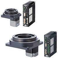
The DGII Series hollow rotary actuator was developed for positioning applications such as rotating a table and swiveling an arm. The DGII actuator has been installed in equipment for the manufacture of semiconductors, electronic parts, and inspection equipment because of its ability to simplify wiring and piping requirements by utilizing the compact, hollow output table. It has also been requested to drive large inertia loads with high torque for conveyors.
In order to support larger tables with larger inertias as well as enhancing the torque, cross roller bearings have been utilized, which offer a high permissible load and high rigidity. The structure, features, and benefits of the DGII Series hollow rotary actuator are explained in this paper.
1. Structure and Features
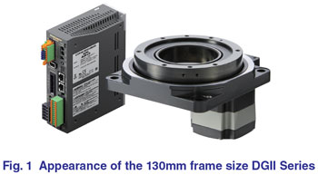
The DGII Series hollow rotary actuator is an electric actuator that is equipped with our closed loop AZ Series (absolute mechanical sensor) or our AR Series (resolver based) motor and driver. Both series come with a pulse input or Network (stored data) type driver.
1.1 Structure
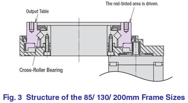
The structure of the 60 mm frame size is shown in Fig. 2 and that of the 85 mm,130 mm and 200 mm frame sizes are shown in Fig. 3.
The DGII Series hollow rotary actuator is a single stage gear mechanism. By using a single stage gear mechanism, factors which affect the positioning accuracy are reduced, and the backlash is decreased by using a low-backlash mechanism developed by Oriental Motor.
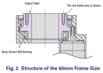
As shown in Fig. 2 and Fig. 3, the bearing support method differs between the 60mm and the 85/130/200mm frame size types. The 60mm frame size type uses a deep groove ball bearing. The 85/130/200mm frame sizes use a cross roller bearing. When combined with an output table, the cross roller bearings allow the rigidity of the output table to be high.
1.2 Features
1.2.1 Common Features of the DG II Series
The DG II Series hollow rotary actuators have the following features:
(1) Direct Coupling
By rotating the output table directly, the table or arm of the equipment can be attached directly to the rotating part of the actuator.
(2) Large Diameter Hollow Structure
A hollow bore with a large diameter is provided on the output table by using a single stage gear mechanism and enlarging the diameter of the driven gear. The hollow area can be used for simplifying the wiring and piping of the machine.
(3) High Accuracy Positioning
The gear teeth use precision processing and the backlash is removed by applying a constant force to reduce the gap between the motor pinion and the driven gear. The repetitive positioning accuracy from one direction is ±15 arc-sec and the lost motion when positioning from both directions is 2 arc-min, so the DGII Series can be used in applications requiring high accuracy positioning.
(4) Short Positioning Time
The DGII Series uses an αstep stepper motor, which has a built-in rotor position detection sensor and can make short positioning times possible. The αstep motor and driver combination monitors feedback information for the rotor speed and position. If the motor is about to lose synchronism, the driver will immediately switch to closed loop mode to prevent the loss of synchronism, allowing short positioning times to be possible.
1.2.2 Features of the High Rigidity Type
The high rigidity type DGII Series actuators in frame sizes of 85mm, 130mm and 200mm have the following feature:
(1) High Permissible Load and High Rigidity
The high rigidity type DGII Series uses cross roller bearings in conjunction with the output table as shown in the drawing in Fig. 3. Cross roller bearings are made by arranging mutually-perpendicular rollers between the inside and the outer rings. Since the rolling surface is always in contact with a roller, it will have high load carrying capability and high rigidity. Also, the bearing can receive the load in any direction and allows for a compact design of the actuator.
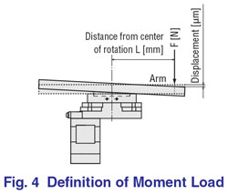
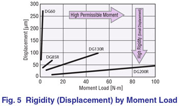
With this cross roller bearing, 500 N of thrust load is permitted for the 85 mm frame size, 2000 N for the 130 mm frame size, and 4000 N for the 200 mm frame size. Also, for loads that are off center creating a moment load as shown in Fig. 4, 10 N∙m is permitted for the 85mm frame size, 50 N∙m for the 130 mm frame size, and 100 N∙m for the 200 mm frame size. The rigidity (displacement value) to the moment load is improved significantly. Fig. 5 shows the displacement value to the moment load at a position 200 mm away from the rotation center. Compared with the 60 mm frame size using the deep groove ball bearing, the displacement value becomes smaller.
(2) Improvement in Mechanical Accuracy
Since the cross roller bearing is combined with the table, the number of parts can be reduced, eliminating many factors that influence the mechanical accuracy of a table. The deflection accuracy is not affected by the assembly and can be based solely on the bearing specification. The surface deflection and the inner (outer) diameter deflection is 15μm, which is 1/2 of the 60mm frame size (standard type). Furthermore, parallelism to the mounting surface also improved to 30μm since it is determined by the two accuracies of the cross roller bearing and the gear case.
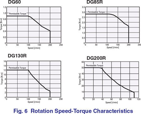
(3) High Permissible Torque
Compared to 0.9 N∙m for the 60 mm frame size, high permissible torques of 2.8 N∙m (about 3 times) for the 85 mm frame size, 12 N∙m (about 12 times) for the130 mm frame size, and 50 N∙m for the 200 mm frame size are achieved.
2. Short Positioning Time
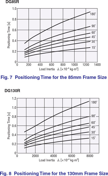
While high permissible torque has been obtained, it also became possible to position a larger inertia load in a short time. Fig. 7 and Fig. 8 show the positioning time vs. inertia load moment when driving the 85 mm and 130 mm frame sizes at a positioning angle of 15° - 180°, respectively. This is the shortest positioning time achieved when setting an acceleration and deceleration time, t1, so that the safety margin of the calculated acceleration torque, Ta, is1.5 times the torque which can be generated at the operating speed, N2. After calculating the inertial moments of the table, arm, work and jig etc. on the table, the positioning time can be obtained from the curves for and positioning angle. For example, for the 85mm frame size, the shortest positioning time of 0.52s is obtained from the graph when operating an iron disk which is 315 mm in diameter and 10 mm thick (JL=76∙0-3 kg∙m2, equivalent to 30 times of the inertia moment of the actuator) at a positioning angle of 90°. In the same manner, for the 130 mm frame size, the shortest positioning time of 0.63s is obtained when operating an iron disk, which is 500mm in diameter and 10mm thick (JL=485∙0-3 kg∙m2,equivalent to 30 times of the inertia moment of the actuator) at a positioning angle of 90°.
3. Change of Positioning Accuracy with Time
Although the DGII Series hollow rotary actuator uses a gear mechanism, both the drive gear and the driven gear are heat treated, which provides resistance to frictional wear of the tooth surfaces and reduces the change in positioning accuracy with time.
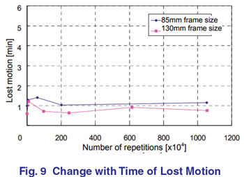
A durability test was performed by attaching an inertia load to the output table which repeats bi-directional operation at a fixed angle so that the acceleration and deceleration torque equal the permissible torque shown in the operation conditions in Table 1. The change
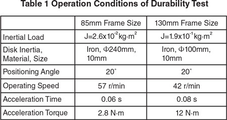
with time of the lost motion is shown in Fig. 9. If frictional wear progresses in a gear mechanism, backlash will be created and lost motion will increase. However, for the DGII Series, even after 10 million cycles, the change with time of the lost motion is still small and the gear's frictional wear is reduced.
4. Comparison with a Timing Belt/ Pulley Mechanism
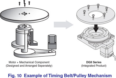
When a table or a large inertia moment is to be moved, or a hollow structure is needed, a motor whose shaft is offset to the rotation axis of the equipment is often used by implementing a timing belt/pulley mechanism, as shown in Fig. 10. Since the timing belt/pulley mechanism transfers torque by a belt, which may be influenced by the expansion and contraction of the belt, the rigidity of the mechanism is low and the motion response becomes poor when compared with the motion response of the DGII Series hollow rotary actuator. In addition, the belt/pulley mechanism needs maintenance, such as belt tension adjustment and replacement, etc.
The following shows the design simplification when positioning an inertial load between a timing belt/ pulley mechanism and the DGII Series hollow rotary actuator.
4.1 Comparison of Response Characteristic of Positioning Operation for Inertial Load
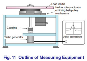
By using the apparatus shown in Fig. 11, the differences in the response characteristic when positioning an inertia load between the prototype timing belt/ pulley mechanism and the 130mm frame size DGII Series hollow rotary actuator were measured.
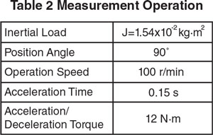
Since the gear ratio and the output torque are the same, the rigidity differences between the two mechanisms can be seen. Each response characteristic was measured with the operation conditions shown in Table 2.
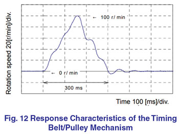
The response characteristics of the timing belt/pulley mechanism are shown in Fig. 13. In the acceleration/deceleration area, the load vibrates, and the load overshoots and undershoots when stopping.
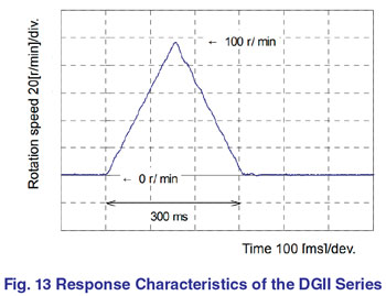
On the other hand, the response characteristics of the DGII Series hollow rotary actuator are shown in Fig 15. During acceleration/deceleration, the motor does not vibrate and there is no overshooting or undershooting like the timing belt/pulley mechanism when stopping, indicating that the load is stable.
Since the gear ratio and the output torque are the same for the two systems and the response characteristics were measured under the same operating conditions, the vibration seen during acceleration, deceleration, and stopping of the timing belt/pulley mechanism could arise from the low rigidity of the belt/pulley mechanism.
In addition, the response characteristics may change with the timing belt/pulley mechanism depending on the belt tension and the stretching of the belt with time. Therefore, periodical maintenance is needed to readjust the belt tension.
Therefore, the response characteristics of the DGII Series hollow rotary actuator can be an improvement to a timing belt/pulley mechanism and can shorten the positioning time. In addition, maintenance is unnecessary and the reliability of equipment can be improved.
5. Comparison with a Direct Drive Motor
Since direct drive motors can receive a load directly, generate high torque without a gearhead, and utilize the hollow structure for wiring and piping, they are being used in the industrial equipment field as a positioning system. Since a direct drive motor has a high-resolution built-in sensor and uses closed loop control, precise positioning operation can be performed.
Gain adjustment is required to fully utilize the performance. Auto tuning functions have been added in recent years. However, there is a question of how reliable the tuning settings are when the load is changed. Changing the inertia load can cause the motor to “lurch” if the gains are not readjusted.
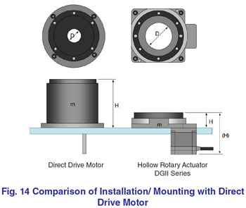
Fig. 14 shows a comparison of the installation of the two devices. The mass of the DGII Series hollow rotary actuator is 1/2 - 1/3 of a direct drive motor. Although the full length is equivalent, the DGII Series hollow rotary actuator is installed by letting the projecting part of the motor extend below the bottom of the mounting plate. This makes the height from the mounting surface 37 mm, about 1/3 of a direct drive motor. In addition, the diameter of the through hole is about twice as large as that of a direct drive motor. This allows for a linear motion mechanism such as ball screw, as well as wiring and piping to easily pass through the opening. The DGII Series can achieve space saving as well as flexibility allowing for equipment design to be improved.
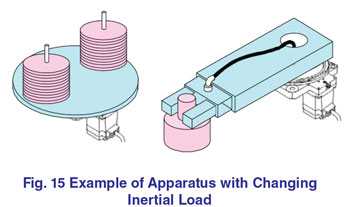
5.1 Comparison of Response Characteristics to Change of Inertia Load
As shown in Fig. 15, if the load on an index table is increased or decreased, or the load is attached or carried at the end of an arm, the inertia load will change. Since the DGII Series hollow rotary actuator operates through a gear, it is not easily influenced by the change of an inertia load, and stable positioning operation is possible. Although an auto tuning function is available on a direct drive motor that enables servo gains to be adjusted quickly, the gain settings presume a fixed load on the table, and do not vary with any changes of the load. When an inertia load is changed significantly, it may cause overshooting, undershooting or lurching, and stable positioning operation may not be possible.
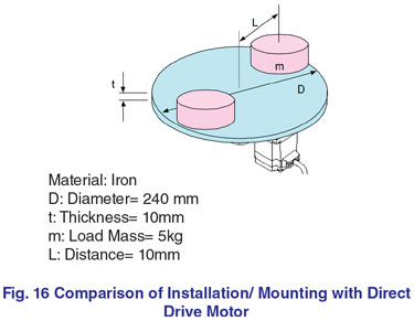
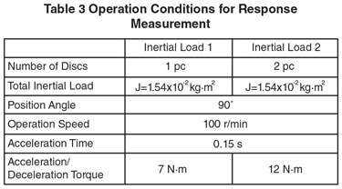
A comparison of the response characteristics to the change of an inertia load using a 130mm frame size DGII Series hollow rotary actuator and a direct drive motor that produce equivalent torque was performed. As shown in Fig. 16, the response characteristic was measured with the operation conditions shown in Table 5 where the number of the discs put on the table is one and two pieces. The apparatus shown in Fig. 15 was used for the measurement in the same manner in 5.2.
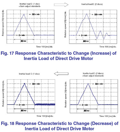
The response characteristic to a change of the inertia load of a direct drive motor is shown in Fig. 17 and Fig. 18. Fig. 17 shows the case where a positioning operation was performed with two discs after adjusting to the optimal gain for the inertia load of one disc.
It turns out that the overshooting and undershooting occur as the inertia increases. Next, Fig. 19 shows the case where a It turns out that the overshooting and undershooting occur as the inertia increases. positioning operation was performed with one disc after adjusting to the optimal gain for the inertia load of two discs. This caused a lurching motion and the positioning operation was not able to be completed.
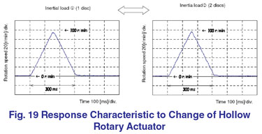
On the other hand, Fig. 19 shows the response characteristics of the 130 mm frame size DGII Series hollow rotary actuator. In this case, it turns out that stable positioning operation was performed with no change in response even if the inertia load is changed.
It turns out that the overshooting and undershooting occur as the inertia increases. Next, Fig. 19 shows the case where a It turns out that the overshooting and undershooting occur as the inertia increases. positioning operation was performed with one disc after adjusting to the optimal gain for the inertia load of two discs. This caused a lurching motion and the positioning operation was not able to be completed.
On the other hand, Fig. 19 shows the response characteristics of the 130 mm frame size DGII Series hollow rotary actuator. In this case, it turns out that stable positioning operation was performed with no change in response even if the inertia load is changed.
6. Summary
The DGII Series hollow rotary actuator can now be used in applications that require high torque and high rigidity by adding the “high rigidity type” frame sizes 85 mm, 130 mm and 200 mm to the product lineup in response to the needs of the market. In order to support a large table or a long moment arm, it is necessary to have high rigidity with a high permissible load as well as increased torque. The DGII Series’ feature of direct coupling and hollow through hole remained intact and the “high rigidity type” offers high permissible load by utilizing a cross roller bearing in combination with the output table.Moreover, when compared to a timing belt/pulley mechanism, which requires an elaborate table support mechanism, it is possible to shorten the time required to design a mechanism and procure parts. Maintenance, such as tension adjustment and exchange of a belt, etc. is unnecessary and because of high rigidity, improvement in the reliability and reduction of positioning time has been obtained.
In addition, when compared to a direct drive motor, the hollow opening diameter is large, and it is lightweight and compact. Space savings can be attained while the flexibility of equipment designs can improve. Also in respect to ease of use, servo gain adjustment is not needed, and stable positioning operation is possible even in applications with changing inertia loads.
Hollow Rotary Actuator