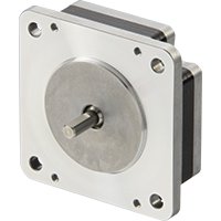
Development of the PKP Series Compact and Flat Connector Equipped Stepper Motor
Oriental Motor developed the PKP Series compact and flat connector equipped stepper motor without changing the motor size in response to greater demand for easier routing of the lead wire and a lower height of the connector unit in the PKP Series. In order to achieve a lower connector height, we revised the motor structure as well as the connector's terminal material and shape to support high electrical current. The new PKP Series motor also features improved torque and vibration characteristics thanks to the optimized magnetic circuit design as well as an increased permissible load in the axial and radial directions to the output shaft. This article explains the structure and characteristics of the PKP Series compact and flat connector equipped stepper motor.
1. Introduction
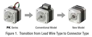
A stepper motor is capable of position and speed control with an open loop system. For this reason, it is adopted in a variety of applications including automatic ticket gates and monitoring cameras. In particular, Oriental Motor's hybrid stepper motor features high torque and accuracy. The conventional PKP Series motors (hereafter the “conventional model”) have improved the characteristics of the PK Series as well as adopted the approach, equipping the motor with a connector and using a connection cable to connect with the driver (hereafter “connector type”) instead of directly drawing out the lead wire from the motor (hereafter “lead wire type”) in order to improve the workability during motor installation and removal. With the newly developed PKP Series compact and flat connector equipped stepper motor (hereafter the “new model”; see Figure 1.), we aimed to achieve a shorter connector unit, higher torque, and improved permissible load at the output shaft, all of which were in high demand with the conventional model.
2. Compact and Flat Connector Equipped Stepper Motor
2.1. Advantages of the Connector Type
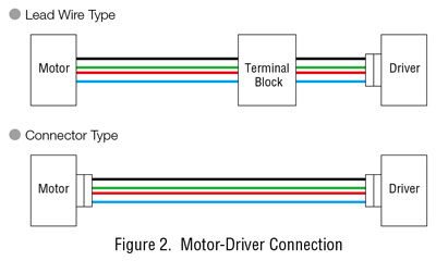
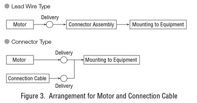
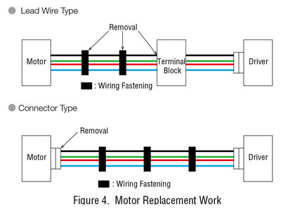
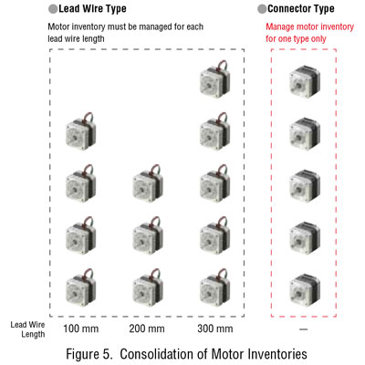
In the case of a lead wire type model, generally, a junction terminal block or a connector is used to connect the motor to the driver. For a connector type, a connection cable is used to directly connect the motor and the driver. (See Figure 2.) The advantages of the connector type, which allows for easy connection and disconnection of the motor and connection cable, are described in Table 1. The connector type is superior for its ease in arranging for parts, replacement work, and inventory management. (See Figure 2 to Figure 5.)

2.2. Compact and Flat Connector Supporting High Electrical Current
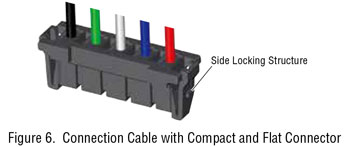
For the conventional model, there were demands for a smaller size as well as improvements in routing direction and in the connection and disconnection of the connector. In addition, as the application of stepper motors has become wider in recent years, the demand for higher torque at higher rotation speeds grew, generating a need for a connector that supports higher electrical current in the motor. Since the downsizing of the connector and its support for a higher electrical current are not achievable with commercially-available connectors, Oriental Motor jointly developed a connector suitable for this motor with Hirose Electric Co., Ltd. The developed connector adopts a side locking structure for improved ease of connection and disconnection, which also resulted in a smaller size and lower profile. (See Figure 6.)
For the material of the terminal, we adopted a low resistance copper alloy to ensure a sufficient contact surface area between the terminal and pins while keeping the contact resistance low. This enabled the development of a compact and flat connector that supports higher electrical current. While the conventional model had to use different connectors according to the current specifications, the newly developed connector can be used with motors of different current specifications.
2.3. Structure and Features of the Connector Unit
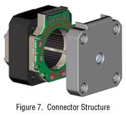
The new model achieves lower height by incorporating the compact and flat connector into the motor. Additionally, the connection cable outlet direction is made to be perpendicular to the output shaft in order to improve wiring workability. (See Figure 7.)
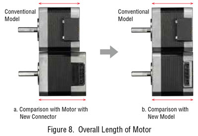
If the motor was equipped with the new connector based on the structure of the conventional model, the overall length of such a motor would be longer (Figure 8-a). By pursuing thin-walled casting for the bracket in order to provide space for the coil, the overall length of the motor was kept to the same length as the conventional model while also achieving a lower height for the connector unit (Figure 8-b). Furthermore, the connection between the PCB and coil was improved to support higher electrical current.
The conventional model was suitable for drawing out and wiring the connection cable in the direction of the output shaft, but at the same time, this restricted the direction that the connector can be accessed to the motor output shaft direction, which also limited the routing of the connection cable (see Figure 9). In addition, in cases where the overall length of the motor is too short, the gap between the mounting plate and connector becomes too narrow for easy connection or disconnection (see Figure 10).
With the new model, the connection cable outlet direction is perpendicular to the motor side, which improves the flexibility of connection cable routing, making it easy to connect and disconnect the connector.
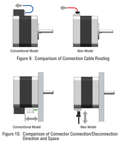
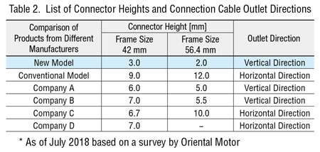
Table 2 shows the connector heights and outlet directions of motors from different manufacturers. The connector height of the new model is 3.0 mm for 42-mm frame size and 2.0 mm for 56.4-mm frame size.
3. Improving the Motor Characteristics by Optimizing Magnetic Circuit Design
For stepper motors, the use of the bipolar drive is increasing compared to the unipolar drive due to its utilization efficiency of motor coils. The mainstream nowadays is the microstep drive, which gradually increases the current of each phase to produce finer step angles―a transition from the half step drive or the full step drive, which switches excitation while maintaining a constant current in each phase. With the new model, we aimed for a design that realizes high torque and low vibration with the microstep drive.
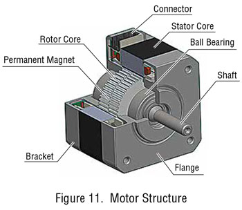
The basic structure of the motor is shown in Figure 11. The rotor consists of a permanent magnet disk between two rotor cores. The permanent magnet is magnetized to the axial direction of the shaft. In general, the torque increases with the size of the permanent magnet and the length of the rotor cores. However, because the amount of magnetic flux is proportional to the size of the permanent magnet, the torque does not increase even when the rotor is extended more than necessary.
On the other hand, if the frame size of the motor stays the same while a larger permanent magnet is used, the shaft diameter must be smaller, which results in reduced shaft strength. We optimized the magnetic circuit design while working with such constraints, point of the θ -T characteristics of AB and AB. This intersecting point is the maximum torque generated by rotation and is called the pullout torque. The pullout torque of a full step drive 2-phase motor is approximately 70% of the maximum holding torque.
The basic structure of the motor is shown in Figure 11. The rotor consists of a permanent magnet disk between two rotor cores. The permanent magnet is magnetized to the axial direction of the shaft. In general, the torque increases with the size of the permanent magnet and the length of the rotor cores. However, because the amount of magnetic flux is proportional to the size of the permanent magnet, the torque does not increase even when the rotor is extended more than necessary. On the other hand, if the frame size of the motor stays the same while a larger permanent magnet is used, the shaft diameter must be smaller, which results in reduced shaft strength. We optimized the magnetic circuit design while working with such constraints.
3.1. Improving the Torque Characteristics
3.1.1. Differences in Pullout Torque Based on Drive System
A stepper motor rotates by switching the excitation sequence for motor coils. Using the angle-torque characteristics (θ -T characteristics), the following explains the step-like movement and the generated torque for each drive system(2) .
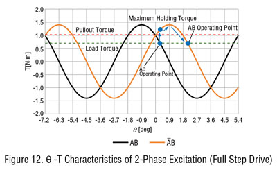
A 2-phase stepper motor is generally driven with 2-phase excitation. The θ -T characteristics for 2-phase excitation are shown in Figure 12. The maximum value for the characteristics is called the maximum holding torque. Current flowing in phase A and phase B is expressed as AB while current flowing in the opposite direction of phase A is expressed as A. If excitation is switched to AB during AB excitation, the rotor moves by attraction to the excitation stabilization point. With each excitation phase switch, the stabilization point moves by 1.8°. The drive system is called the full step drive, and by repeating this operation, the rotor continuously rotates. When a load is applied, the intersecting point of the load torque and the θ -T characteristics is the operating point. The rotor can withstand up to the intersecting point of the θ -T characteristics of AB and AB. This intersecting point is the maximum torque generated by rotation and is called the pullout torque. The pullout torque of a full step drive 2-phase motor is approximately 70% of the maximum holding torque.
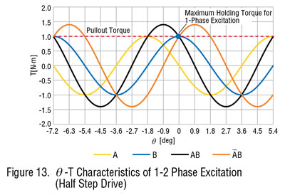
The 1-2 phase excitation occurs in half step drive where 1-phase excitation and 2-phase excitation are alternately repeated and the rotor rotates by 0.9° (expressed as 0.9°/ step). The θ -T characteristics in this case are shown in Figure 13. The pullout torque in half step drive is the maximum holding torque of 1-phase excitation.
As explained above, the full step drive and half step drive have equal pullout torque.
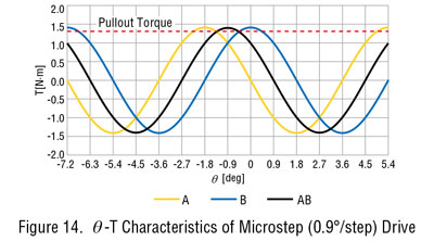
The input current of a motor is determined by the temperature rise caused by motor winding loss (copper loss). Copper loss is proportional to the square of the current, and therefore it is possible to increase the 1-phase excitation current by 2 times to make the copper loss from 1-phase excitation equal to that of 2-phase excitation. The θ -T characteristics when the 1-phase excitation current is multiplied by 2 are shown in Figure 14. The pullout torque is increased by this drive operation.
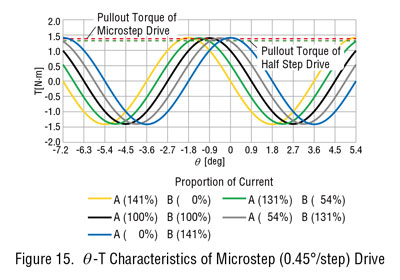
The microstep drive has an even higher resolution (finer step angle). By setting intermediate levels for current switching points, the step angle is made finer as the current value changes. The θ -T characteristics when the step angle is 0.45° are shown in Figure 15. A higher resolution produces a higher pullout torque, which comes closer to the maximum holding torque of 2-phase excitation. Because the current comes close to a sine wave, it is sometimes called the sine wave drive.
3.1.2. Improving the Torque Characteristics
In principle, the torque is proportional to the motor input current and is represented by the equation (1) below.
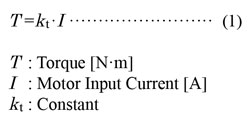
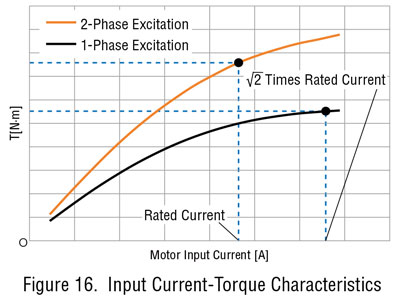
However, in reality the current and torque are not in a proportional relationship as shown in Figure 16, and the torque tends to saturate. This is due to the magnetic characteristics of the electrical steel sheet used in the stator core and rotor cores. If the current in 1-phase excitation is further increased in microstep drive, the torque from 1-phase excitation falls below that from 2-phase excitation, and therefore multiplying the current by √ 2 does not increase the torque by √2 times.
In conclusion, the conventional model has a higher torque saturation with 1-phase excitation compared to 2-phase excitation, which results in the 1-phase excitation torque being lower than the 2-phase excitation torque. The θ -T characteristics including torque saturation are shown in Figure 17. The pullout torque is the maximum holding torque with 1-phase excitation.
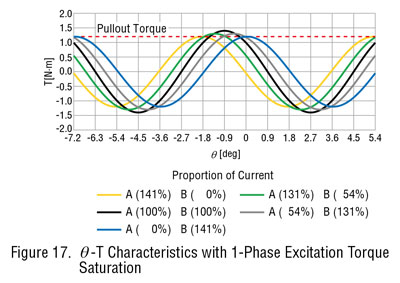
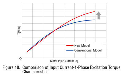
Figure 18 shows a graph comparing the input current torque characteristics of 1-phase excitation with the new model and the conventional model. The new model, having a magnetic circuit design suitable for microstep drive, demonstrates improved linearity that counters the torque saturation observed with the motor input current of the conventional model.
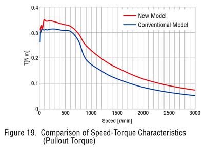
The speed-torque characteristics when the new model is combined with a CVD driver that supports microstep drive throughout the entire speed range are shown in Figure 19. Increased torque over the entire speed range is achieved compared with the conventional model.
3.2. Reducing Vibration Caused by Resonance
In general, stepper motors tend to have increased vibrations with greater torque fluctuations. Vibration can lead to loss of synchronism or noise. In principle, the θ -T characteristics align at equal intervals with different excitation states in microstep drive mode. The stabilization point interval is the step angle. With microstep drive, the phase A current and phase B current are gradually changed, which means that the stabilization point is determined by phase A-B torque balance. The conventional model does not produce phase A-B synthetic torque as per principle due to magnetic saturation, and therefore their stabilization point intervals were not equal (see Figure 20).
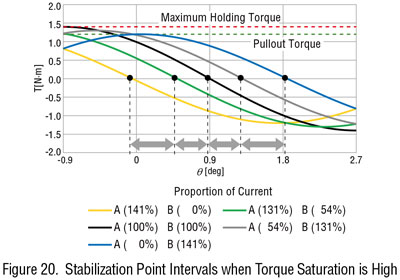
The varied stabilization point intervals indicate a fluctuation in stabilization point travel speed. Torque fluctuation occurs when the travel speed of the stabilization point changes. If the frequency of that torque fluctuation and the motor's natural frequency match, the speed fluctuation of the shaft rapidly increases. This is a phenomenon called resonance.
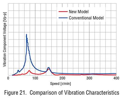
Figure 21 shows the vibration characteristics of the conventional model and the new model. The large vibration around 80 r/min is the vibration caused by resonance. The new model features improved linearity in the current-torque characteristics, which contributes to reduced torque fluctuations and resulting vibrations.
3.3. Improving the Permissible Load
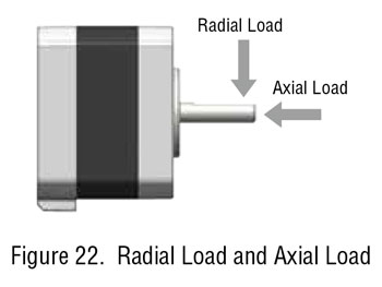
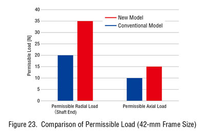
Improvements in the stepper motor characteristics enable a wider application of the product. Naturally, improved permissible load is in demand for the motor output shaft. As shown in Figure 22, permissible load involves the permissible radial load and the permissible axial load. For the new model, ball bearings with a greater basic dynamic load rating were adopted to improve the permissible axial load. The ball bearing also has a greater shaft diameter to improve the permissible radial load. The shaft couplings used by customers have the same output shaft diameter as that of the conventional model, considering the compatibility with former models.
Simply making the shaft diameter larger only ends up reducing the volume of the rotor's permanent magnet and the generated torque. The new model features a magnetic circuit design that is created with the premise of using a larger shaft diameter.
Figure 23 shows a comparison of permissible load between the conventional model and the new model, both with a frame size of 42 mm.
4. Summary
The new model has a low profile connector and provides improved flexibility in the connection cable routing direction while keeping the same overall motor length as the conventional model. Along with an optimized magnetic circuit design, the new model also offers higher torque, lower vibration, and improved permissible load for the output shaft. It is a motor that can be used in more extensive applications. We, at Oriental Motor, will continue working on motor development with the aim to contribute to improving the performance of our customers' equipment.
