AC Motors & Gear Motors > Brake Pack
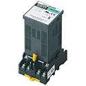
SB50W Brake Pack
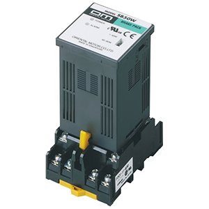
SB50W Brake Pack
The SB50W brake pack provides instantaneous stop, bi-directional operation and electromagnetic brake control functions integrated into one unit. This brake pack can sense when the thermal protector is opened, ensuring the safety of your equipment. For greater convenience, a function has been added to reset alarms using an external signal.
- Instantaneous Stop
- Long-Life, Simple Wiring, Maintenance Free
- Wide Voltage Range of 100 to 230 VAC
Brake Pack Lineup
Item |
Motor Output Power |
Voltage* |
Functions |
|
1/750 HP (1 W) up to 1/8 HP (90 W) |
Single-Phase 100 to 230 VAC |
Instantaneous Stop Bi-Directional Operation Electromagnetic Brake Control Thermal Protector Open Detection |
*Use this product according to the power supply voltage of the applicable motors
Brake Pack Features
Four Functions in One Integrated Unit
The SB50W provides instantaneous stop, bi-directional operation, electromagnetic brake control and thermal protector open detection functions.*
*Thermal protector open detection function (Available only when combined with a motor having a built-in thermal protector) When the motor's thermal protector (overheat protection device) is activated, the SB50W outputs an alarm signal and automatically cuts the power supply to the motor. The motor will not restart by itself, even after the temperature drops and the thermal protector closes. The alarm can be reset with external signals.
Long Life, Simple Wiring and Maintenance-Free
The electronic brake operates on current flow, so it lasts longer than the mechanically operated electromagnetic brake that is subject to wear. This makes the SB50W ideal for indexing applications. The electronic-input type brake pack doesn't use a power relay, so no maintenance is required. Wiring is easy as well.
Link Electronic Brake and Electromagnetic Brake
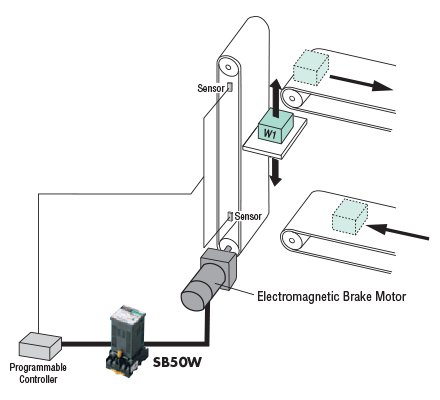
By combining the SB50W with a motor equipped with an electromagnetic brake, you can link the electronic brake with the electromagnetic brake to allow the load to be held automatically following an instantaneous stop. This configuration is ideal for vertical applications in which the load must be held following the instantaneous stop of the motor.
Wide Voltage Range of 100 to 230 VAC
The SB50W covers a single-phase voltage range of 100 to 230 VAC ±10%, accommodating major voltages used throughout the world. Use this product according to the power supply voltage of applicable motors.
Conforms to Safety Standards
The SB50W is recognized by UL and CSA, and the CE Marking is used in accordance with the EMC Directive and Low Voltage Directive.
Switchable Sink/Source Logic
Select sink logic or source logic for the input/output circuit. You can change the setting at any time.
Supports Motors with 1 W to 90 W (1/750 HP to 1/8 HP) Output
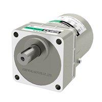
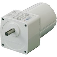
The SB50W can be used with induction motors, reversible motors, electromagnetic brake motors and watertight, dust-resistant motors with an output power of 1 W to 90 W (1/750 HP to 1/8 HP)
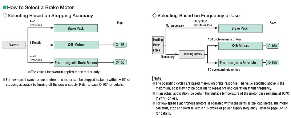
Instantaneous Stop
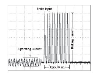
The electronic brake stops the motor instantaneously. A large braking force causes the motor to stop in approximately 0.1 second, allowing for an overrun of 1 to 1.5 rotations. The braking current flows through the motor for approximately 0.4 seconds, after which the power supply to the motor is cut off automatically (The motor will have no holding torque).
How to Read Braking Characteristics (Reference values)
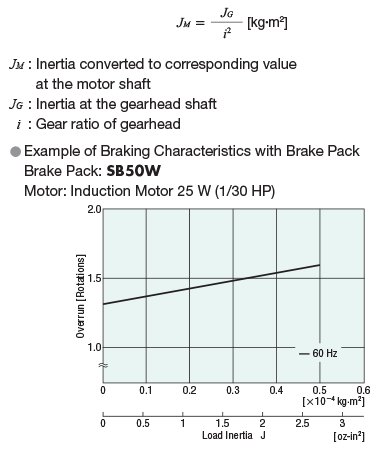
The brake pack provides stable braking characteristics for the instantaneous stop of the motor. The braking characteristics are illustrated by the braking curve, which indicates the amount of overrun corresponding to the load inertia.
The braking time is 4n/f seconds or less.
Where, n: overrun, f : power supply frequency
For example, if the 4IK25GN-AW2U [single-phase 115 VAC, 25 W (1/30 HP)] and SB50W are used together to stop a load with an inertia of J = 0.25×10⁻⁴ kg·m2 (1.37 oz-in2), the overrun and braking time required will be approximately 1.4 rotations and 0.1 seconds, respectively, at a power supply frequency of 60 Hz. In the case of deceleration using a gearhead, refer to the braking characteristics curve after converting the load inertia at the gearhead shaft to its corresponding value at the motor shaft.
Use the following formula to convert the load inertia at the gearhead shaft to its corresponding value at the motor shaft:
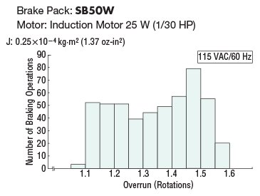
Stopping Accuracy
The figure below shows the stopping position error (variation in stopping position) when braking force is applied to the motor using the brake pack. The diagram shows an overrun distribution when braking is repeated 500 times under the same conditions. Varying stopping positions are caused by the power-supply phase when the switch is operated to apply the brake, which could generate a maximum delay of one cycle (power supply frequency) and variation in initial braking force. The sagging at the center reflects the slot position relationship between the stator and rotor.
Refer to the braking characteristics curve representing the average overrun.
Fuse Capacity
When a brake pack is used to stop the motor instantaneously, a large amount of braking current will flow into the motor for approximately 0.4 seconds. Therefore, when connecting a fuse to the power line, select one with the appropriate capacity by referring to the braking current for the motor being used.
Other Motor Braking Options
In addition to the brake pack, various other brake options are available to suit a variety of applications.
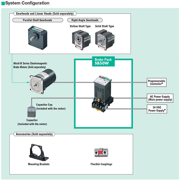
System Configuration
CAD / Manual Search
To locate product CAD and Operator Manuals please search using the product Item Number.
Downloads
Technical Articles
Reference
Compatible Motors