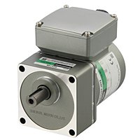
AC Motor Utilization
1. Select a Combination of Features
By combining mechanisms and circuits, AC motors can obtain various additional functions.
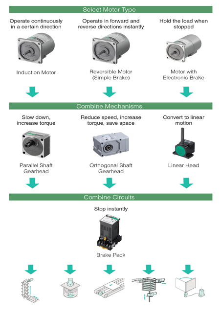
*Depending on the product, the gearhead type and circuit combination may vary.
We will explain the roles and operation principles of "gear head", "electromagnetic brake" and "brake pack" respectively.
2. Speed Reducer Method- Gearheads
The gearhead is a mechanism that slows the rotation speed of the AC motor and increases the generated torque. It is attached to the tip of a gear cutting shaft type motor.
Role of the Gearhead
The gearhead has the role of "slowing the rotation speed" of the motor "to increase generated torque" and "to reduce the overrun amount".
• Reduce Speed
The rotation speed of the AC motor is determined by the power supply frequency, the number of motor poles, and the magnitude of the load.
By combining gearheads, it is possible to slow down the motor's rotation speed by the reduction ratio of the gearhead.
![]()
For example, when the motor shaft rotation speed is 1300 r / min, if you use a gearhead with a reduction ratio of 1/50, the rotation speed of the output shaft of the gearhead will be 26 r / min.
• Increase Generated Torque
The torque of an AC motor has specification values for each product. By combining gear heads, the generated torque can be increased by the reduction ratio of the gear head.
Although it is ideal to multiply the torque by the reduction ratio, loss of power is due to gear friction. Therefore, when calculating, consider the transmission efficiency of the gearhead. In the case of a parallel shaft gear head, the high speed reduction ratio is composed of multiple gears, so loss will increase.

For example, if the torque of the motor shaft is 0.2 N · m, using the gearhead with the reduction ratio of 1/50 and the transmission efficiency of 86%, the torque of the output shaft of the gearhead will be 8.6 N · m.
• Reduce the Overrun Amount
By combining gearheads, it is possible to reduce the overrun amount by the reduction ratio of the gearhead.

When using a gearhead with a reduction gear ratio of 1/50 for an induction motor, a reversible motor, and a motor with an electromagnetic brake, the guideline (reference value) of the overrun amount of the output shaft of the gearhead is as shown in the table below.

How to Read the Gearhead Specification
• Allowable Torque at Gearhead Mounting
Depending on the combination of the motor and the gearhead, the magnitude of allowable torque is different. Calculate the necessary torque from the mechanism condition and confirm that it is within the allowable value.

① Product name It is a combination type name of a motor and a gearhead. Depending on the product, it may be listed as a single item name.
② Rotational speed It is a value obtained by dividing the synchronous rotation speed of the motor by the reduction gear ratio of the gearhead. Actual
rotation speed shows up to 30% less value depending on load size.
③ Reduction ratio It is the reduction gear ratio of the gearhead.
④ allowable torque It is a value obtained by multiplying the rated torque of the motor by the reduction ratio of the gearhead and the transmission efficiency of the gearhead. If it exceeds a certain reduction ratio, it is limited because the gear head exceeds the allowable torque.
⑤ Maximum permissible torque It is the upper limit value of the load torque applied to the gear head. If it exceeds this load, the gear head may be damaged.
• Allowable Radial Load/ Axial Load of Gearhead
Radial load is a load applied in a direction perpendicular to the output shaft. Axial load is the axial load applied to the output shaft. For each gear head, the allowable radial load / axial load magnitude differs. Calculate the load from the mechanism condition and confirm that it is within the allowable value.
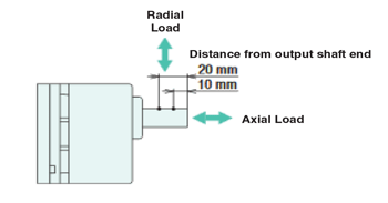

Radial load is always applied to the output shaft when using chains, gears, belts, etc. for the transmission mechanism from the gearhead output shaft.
• Allowable Moment of Inertia of Gearhead
Moment of inertia is a value that represents difficulty of moving or stopping the object. The size of allowable inertia varies for each type of motor. Calculate the moment of inertia from the mechanism condition and confirm that it is within the allowable value.

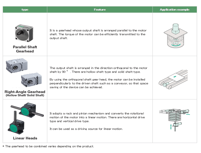
Types of Gearhead
We offer three kinds of gearheads. Benefits other than deceleration can be obtained by using gearheads properly according to load and equipment.
3. Load Holding Function- Electromagnetic Brake
When you want to keep the load of the AC motor, use a motor with electromagnetic brake.
Role of Electromagnetic Brake
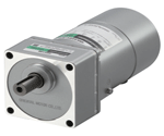
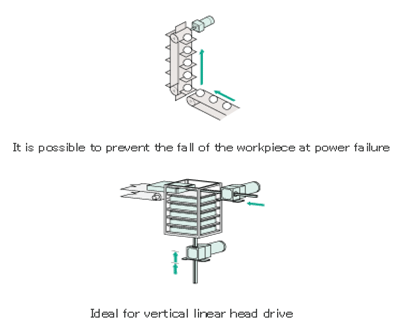
Our electromagnetic brake equipped motor is equipped with a non-excitation type electromagnetic brake. A non-excitation type electromagnetic brake is a mechanism that can hold a load when the power is turned off.
Application Examples:
Operation Principle of Electromagnetic Brake
Structure
Friction brakes are built in the rear of the motor with an electromagnetic brake. Hold the load by pressing the brake lining against the brake hub.The brake lining is integral with an iron armature. The figure below shows the state of the electromagnetic brake when the motor is running.
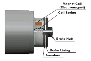
During motor operation, current flows through the exciting coil. The iron armature is attracted to the excitation coil which became an electromagnet by electrification. As a result, the brake lining and the brake hub separate from each other, and the motor output shaft becomes free. While the motor is stopped, the coil spring pushes out the armature. As a result, the brake lining and the brake hub come into contact and hold the load.
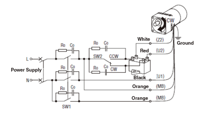
When operating the motor with electromagnetic brake, connect the power line with the electromagnetic brake wire. The electromagnetic brake wire is connected to the excitation coil inside the electromagnetic brake. As long as there is no power connection, the motor shaft remains locked.
4. Instantaneous Stop Function- Brake Packs
When you want to keep the load of the AC motor, use a motor with electromagnetic brake.
Role of a Brake Pack
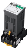
A brake pack is a product with a brake circuit. You can instantly stop the motor and reduce the overrun amount. The below figure compares the overrun amount (reference value) of each AC motor at no load. By combining the brake packs, the overrun amount can be reduced to about 1 to 1.5 revolutions.

Simple Positioning with a Brake Pack
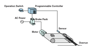
Brake packs can be controlled by upper PLC or the like. It can also be used for simple positioning using an external sensor.
Operation Principle of Brake Packs
The AC motor rotates by the rotating magnetic field generated by AC power. The brake pack generates a fixed magnetic field by applying a large braking current to the motor. The motor stops because lost the rotating magnetic field. After supplying the braking current, commercial power is also cut off.
Internal Configuration of Brake Pack
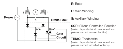
The circuit using the SCR is a circuit that flows the braking current. Only current from one direction flows. The circuit using TRIAC is a supply circuit for commercial power. Current flows from both directions.
When Operating an AC Motor
When operating an AC motor, use the TRIAC circuit. When the trigger signal is given to TRIAC, AC power is supplied to the AC motor. In the case of a single-phase motor, a current that is out of phase due to the capacitor flows in the auxiliary winding against the current flowing in the main winding. This generates a rotating magnetic field and causes the motor to rotate.
When Stopping the AC Motor Instantaneously
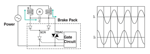
To stop the AC motor instantaneously, use the SCR circuit to shut off the TRIAC circuit. When a trigger signal is given to the SCR, braking current flows in the AC motor. The braking current is a current in one direction. Because this braking current is half-wave rectified, only the in-phase current flows. In addition, since the SCR circuit does not go through the capacitor, there is no phase shift between the main and auxiliary windings. After applying the braking current, turn off the TRIAC signal to shut off the commercial power supply.

During instantaneous stop, a large braking current greater than the operating current flows. The braking current does not flow for less than a second, so heat generation does not increase with one use. However, if driving and braking are repeated in a short time, the heat generation of the AC motor and the brake pack may increase, and the continuous use time may be limited.
