Brushless DC Motors & Gear Motors > Technology > AGV / AMR Designs: Understanding Brushless DC Motor Benefits
AGV / AMR Designs: Understanding Brushless DC Motor Benefits
With an evolving competitive market over the years leading to IOT (Internet of Things) or Industry 4.0., manufacturers are looking for smarter ways to get ahead of their competition. An example of this is the growing trend of Automated Guided Vehicles (AGVs) and Autonomous Mobile Robots (AMRs), as well as an increase in automated storage and retrieval systems in both warehouses and manufacturing facilities. In this paper, we will provide an introduction to AGV/AMR and discuss why features and characteristics of geared brushless DC motors make them attractive for AGV/AMR’s drivetrain designs.
1. What is the Difference between AGVs and AMRs?
AGVs and AMRs are acronyms used to describe mobile autonomous vehicles used primarily to transport products or materials around a warehouse or manufacturing facility. They can help increase safety, efficiency and productivity while reducing product damage and cost. For example, bigger, manually operated vehicles can be replaced by smaller AGVs or AMRs therefore maximizing storage density. These autonomous vehicles can be classified into 2 main categories: “assisted navigation” type and “smart navigation” type.
Assisted Navigation
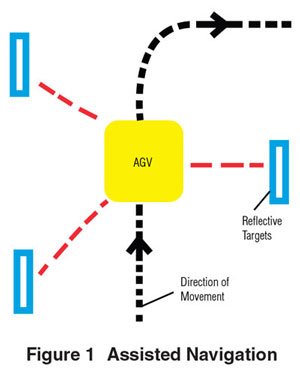
Traditionally, AGV was chosen as the term to describe autonomous vehicles. By definition, an AGV is “guided” by a series of markers that can be detected by sensors. Some applications may require multiple types of markers for the AGV to navigate. The most popular navigation method is laser triangulation. With this method, the laser sensor on the AGV scans for reflective targets, which are placed at known locations in the work area as seen in Figure 1. The vehicle then triangulates the signals from the reflective targets and calculates its exact relative location and path with an algorithm. Other navigation methods are inertial navigation, grid navigation, magnetic tape navigation, embedded wire navigation, map navigation, and optical navigation. These navigation and methods differ by type of sensors or markers used.
Examples of Assisted Navigation Type:
AGV (Automated Guided Vehicles)
AGC (Automated Guided Carts)
LGV (Laser Guided Vehicles)
Smart Navigation
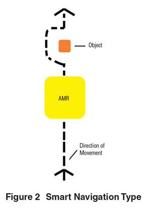
AMRs, are the next advancement in AGV technology. By definition, an AMR is “unguided” and does not depend on markers or reflective targets to guide them to their destinations. In some cases, the requirement of reflective targets or magnetic markers could be difficult to implement. These newer, smarter AMRs now include 2D or 3D mapping as well as more sophisticated cameras, sensors and algorithms in order to make more decisions on their own. AMRs use sensors, with lidar being the most popular choice. Lidar sensors use pulsed lasers and highly sensitive detectors to survey and measure distances from objects. This helps with simultaneous localization and mapping technology in order to both create a map from an unknown environment and maintain a location within that map. With this advanced control, AMRs can determine its own path to avoid obstacles (see Figure 2).
Examples of Smart Navigation Type:
AMR (Autonomous Mobile Robot)
AIV (Autonomous Indoor Vehicle/ Autonomous Intelligent Vehicle)
VGV (Vision Guided Vehicle)
UGV (Unmanned Ground Vehicle)
SDV (Self-Driving Vehicle)
SGV (Self-Guided Vehicle)
2. Five Areas of AGV/AMR Design
AGV’s and AMR’s design can be classified into 5 main sections: battery, controller, sensors, peripheral mechanisms, and drivetrain.
1. The battery section of the vehicle is the power source that supplies the necessary power for every electrical component on the vehicle. Types of batteries used include flooded lead acid, NiCad, lithium-ion, inductive power and fuel cell. Before the battery depletes, some AGV/AMR offer switching of batteries in order to continue operation, some can be programmed to return to a charging station.
2. The controller performs the function of a brain for the AGV/AMR. A PLC, PAC or IPC processes incoming sensory data and contains the necessary programming to work autonomously. A HMI programming interface, such as a touchscreen or pendant, is used for data input.
3. Various types of sensors act as the eyes of the vehicle, which provides data on the vehicle’s environment. Obstacles can be detected in 2 methods: optical detection with laser sensors, or mechanical bumper detection with pressure sensors. A safety standard, ANSI/ITSDF B56.5-2012, serves as a guide for operational requirements of an AGV/AMR. In addition, feedback devices such as encoders, resolvers or hall-effect sensors are used to calculate distance traveled as well as verify speed of the vehicle.
4. Any motion external to the drivetrain would be classified as peripheral mechanisms. On most vehicles, there may be a lift mechanism to lift the load, and perhaps a tray feeder, door or arm that is also controlled by motors or actuators.
5. The drivetrain contains drive shafts, wheels, electric motors and gearheads. These components move and steer the vehicle. Direction of the vehicle is typically controlled through synchronized or independent rotation of its wheels.
Drivetrain Design
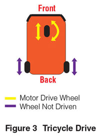
Tricycle Drive is the most common drivetrain design. One drive wheel and 2 non-driven wheels are used in a triangular configuration. The sole front drive wheel is used to both steer and move the vehicle. One gearmotor is necessary to rotate the drive wheel, and another motor is necessary to steer. The 3 wheels in this design provide enough maneuverability for most AGV/AMR applications.
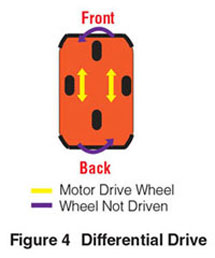
Differential Drive steers the vehicle using differential speed and direction of the 2 drive wheels. These include two geared motors for the drive wheels. It is extremely maneuverable since it can rotate around the center of the vehicle, but angular positioning is less precise.
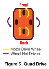
Quad Drive uses 2 steer and 2 drive motors. It is also extremely maneuverable, but more complex than other drive configurations. The vehicle can move about the center of its axis and sideways as well.
3. Why Brushless DC Motors?
Battery Friendly & Better Heat Dissipation
Batteries produce DC voltage, which makes them an ideal power source for DC motors. 24 or 48VDC batteries are commonly adopted which brushless DC motors can easily work with.
High operating temperature is a concern for heat sensitive components in an AGV/AMR. Compared to brushed DC motors, brushless DC motors offer better heat dissipation since the windings are usually located outside of the rotor. Lower operating temperatures can help prolong the life and duty cycle of the motors. Other options are stepper motors and servo motors. However, conventional stepper motors typically generate quite a bit of heat, and servo motor performance comes at a higher cost.
Compact Design
Minimizing footprint of components and the vehicle itself is also important for applications with space constraints. The compact size of brushless DC motors naturally attracts AGV/AMR designers.
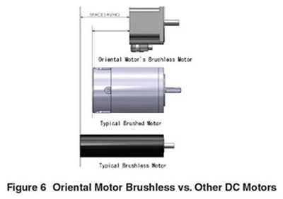
Oriental Motor leads the industry by offering brushless DC gearmotors in a unique compact case. The shorter length and wider motor case allows for a bigger rotor with higher inertia that can handle high load applications when compared to traditional long cylinder-like brushless DC motors. Motor length is reduced compared to brushed motors (see Figure 6).
No Maintenance or Arcing
To limit downtime for the AGV/AMRs, brushless DC motors offer an advantage to brushed DC motors because they do not require brush maintenance. Brushes wear out over time with use and must be replaced periodically. Brushless DC motors do not use brushes for electrical commutation. Therefore their useable life is much longer. This benefit can cut labor costs for motor maintenance and reduce downtime. Without the dust from the brushes, as well as arcing issues, brushless DC motors can also be used safely in more environments than brushed DC motors. By using a driver to electrically commutate its windings instead of brushes, brushless DC motors also generate less electrical interference and audible noise than brushed DC motors.
Wide Speed Range, Flat Torque, Continuous Duty Characteristics with Closed Loop Performance
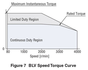
When moving objects from point A to B, an AGV/AMR is continuously running and carrying loads. In order to carry its maximum payloads at different speeds, the motor must be able to handle various speeds at constant torque. The wide speed range and flat torque characteristics of brushless motors allows designers maximum flexibility in their designs. Brushless motors are continuous duty due to their high efficiency. They can be run continuously without additional heat sinks which can help increase productivity. The torque curve of a brushless motor is shown in Figure 7.
Closed-loop performance of a brushless DC motor is often achieved with feedback provided by hall-effect sensors. These sensors are inside the back of the motor and provide a signal to the brushless driver for speed regulation. The basic feedback resolution with Oriental Motor’s brushless motors is 30 pulses per revolution (PPR). The driver can regulate speeds at +/- 0.5% fluctuation. This is considered servo grade accuracy.
Motor Feedback for Zone Regulation
Zone regulation requires a vehicle to sense objects in different proximity zones in order to determine warning or stopping behavior. When an obstacle is in the vehicle’s proximity warning zone, it is recommended to have the vehicle slow down and send an alarm to notify personnel. When an obstacle is in the stop zone closest to the vehicle, the vehicle should immediately stop. Zone detection can be further customized by the designer.
In order to achieve zone detection, an option is through feedback. The drive motors need enough feedback resolution to detect different zones quickly within the map. Motor feedback such as a hall-effect sensor IC can provide digital pulses back to its driver for tracking purpose. The standard feedback resolution of 30 pulses per revolution (PPR) at the motor shaft can be multiplied by the gear ratio of the gearhead. A typical AGV or AMR application needs high torque and low speed so high gear ratios are usually chosen for the gearmotor. In the next example, we will show you how to convert feedback resolution from the motor shaft to the drive wheel.
Specifications:
30 PPR (at the motor)
50:1 gear ratio
10" diameter drive wheel
Conversions:
1. Convert from motor shaft pulse resolution to gear shaft pulse resolution:
30 PPR x 50:1 gear ratio= 1500 PPR
2. Convert gear shaft resolution to degrees per pulse:
360 degrees / 1500 PPR = 0.24 degrees per pulse
3. Convert from degrees per pulse to linear distance per pulse:
(10" x Π) / 1500 PPR = 0.02" per pulse
In most cases, the 0.02" drive wheel linear resolution is sufficient for zone regulation detection.
When stopping an AGV/AMR, other factors such as overrun come into play. The overrun with brushless motors at 2500 RPM is about 2.6 revolutions at the motor shaft when operating within permissible load inertia. For a 10" diameter wheel and a 50:1 gearmotor, this is equivalent to 1.63" from the time it receives a stop command.
(2.6 revs / 50:1 ratio) x 10” x Π =1.63”
The overrun varies depending on the speed, load inertia and motor size.
Integrated Braking
ANSI/ITSDF B56.5-2012 lists requirements for an emergency brake, parking brake and service brake on an AGV/AMR. While hydraulic or pneumatic actuators are commonly used for emergency brake requirements, motors with electromagnetic brakes can be used to fulfill some of these requirements. A power-off-activated electromagnetic brake uses friction to stop and hold the motor shaft in position, which makes it ideal for parking brake requirements. In most cases, the motor and driver will offer functions such as dynamic (electrical) braking. In dynamic braking, instantaneous stop is achieved by turning off current to the motor and shorting all phases together. This results in a locked rotor condition which prevents motor rotation. A combination of dynamic braking with deceleration and electromagnetic braking, can be used to fulfill service brake requirements.
Since friction wears down the brake, it is recommended to use a dynamic brake to stop the motor, then activate the electromagnetic brake to park the AGV/AMR. Purchasing off-the-shelf motors with preassembled electromagnetic brakes guarantees performance and shortens lead time. Time spent on installation and testing are eliminated as specifications are pretested and approved by the motor manufacturer.
4. Gearing Options
Variety of Shafts, Gears, and Mounting Types
Choosing the right gearhead is the next important decision to a successful drivetrain design. There are a variety of gearheads available in the market offering various configurations including solid or hollow shaft as well as spur, worm, helical or hypoid gears. While the shaft type affects the drivetrain design, the type of the gear can affect its performance. For example, hollow shaft gearheads can help minimize footprint by eliminating a coupling. Gear backlash can affect zone detection in bidirectional operation, and gear efficiency can affect payload capacity.
Other than shafts and gears, the type of mounting orientation and mounting type of a gearhead needs to be considered. The mounting orientation can be parallel or right angle, and its mounting type can be foot mount or flange mount. Foot mount type gearheads eliminates the need to buy or build a mounting bracket, and flange mount type gearheads can help minimize footprint.
Designers need to choose a type of gearhead that best fits their drivetrain design as well as provide the necessary performance. In most cases, a spur, helical or hypoid gears are sufficient while inefficient worm gears are not recommended for high load applications. As with built-in brakes on motors, purchasing a motor and gear assembly from the same manufacturer guarantees specifications and saves time.
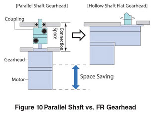
Space Saving Parallel Hollow Shaft Flat (FR) Gearhead
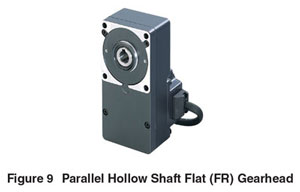
A popular choice of gearheads used for AGV/AMR designs is the hollow-shaft type. While many hollow-shaft gearheads are right-angle, a unique gearhead and motor combination is offered by Oriental Motor. It is a parallel flat style gearhead designed to save space, offer high torque, and be back driven if needed. This can be found in the BLV & BLH Series. The unique FR flat style parallel hollow shaft gearheads can mount a drive shaft and wheel from either side. It also can reduce assembly time and labor costs by reducing the components required for assembly, such as couplings, pulleys or belts, that connect the gear shaft to the drive shaft (see Figure 10).
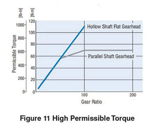
High Permissible Torque
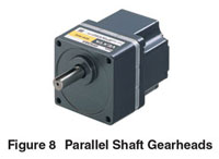
These FR gearheads offer higher, unsaturated permissible torque when compared to parallel shaft gearheads (see Figure 11). The FR gear case has been made more rigid, and the longitudinal layout allows for bigger gears. Both design changes lead to higher permissible torque. The extra space in the FR gearhead also allows larger bearings which result in higher overhung load and increases the life of the gearhead. This gear assembly design also features reduced noise due to a fine finish on the surface of the motor pinion shaft. These features allow the AGV/AMR to offer low noise operation with increased load capacity and extended life.
5. Brushless Motor Drivers
User Friendly and Flexible
Since multiple operators need to be familiar with using, controlling or programming these autonomous vehicles, controls must be user friendly. Ease of use and plug & play are attractive features for brushless motor controllers (commonly called motor drivers). Some drivers allow the capability of I/O customization for specific applications.
Control of speed and direction of the motors need to be flexible and easy to implement in order to shorten engineering development time. Some autonomous vehicles use an analog input signal (I/O), in the form of either a potentiometer or an externally fed analog voltage 0~10 VDC; and some use stored speed data which can be digitally programmed on the dedicated driver or via an industrial fieldbus network. These features are included in standard off-the-shelf drivers and addresses concerns of flexibility and ease of use.
Beneficial Functions Designed for AGV/AMR
Vector control is a built-in feature used for ramp operation while keeping speed constant. This is an important feature and beneficial to ensuring the AGV/AMR is capable of carrying a load at a constant speed up and down ramps.
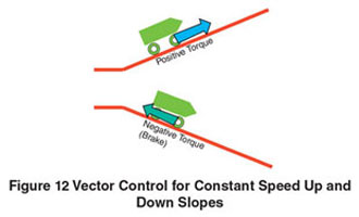
When traveling on ramps, an issue is with back EMF or back electromotive force that occurs when a motor is backdriven by an external force such as gravity. This causes the motor to generate voltage which heads directly back to the driver circuit. Back EMF can also occur when physically pushing the AGV/AMR that is unpowered or suddenly stopping with a large inertia load. If back EMF is not handled properly, it could lead to product damage. If necessary, a method to reduce back EMF is to program a longer deceleration time or to include driver functions which delays the motor response.
There are functions such as speed response modes to aid with back EMF. Low response delays the motor response by applying a primary delay filter to the speed command information which is used within the driver. This function helps the motor to respond at a slower rate to help reduce back EMF generated.
Monitor Function Reduces Downtime
Monitoring the condition of the motors and drivers in the vehicle allows for preventative maintenance and can eliminate down time. When alarms trigger for the motors, the motors will typically shut down until the issue is resolved. It’s important to know of potential issues before these alarms are triggered, and this is where monitoring comes in. For this to happen, a closed-loop system with motor feedback is necessary. Both the motor and driver status data needs to be relayed to the master controller. This can be done with a PLC either through I/O or through an industrial fieldbus network such as Modbus RTU or EtherCAT.
Some motor and driver systems can provide as much as temperature feedback and mileage data to help prevent issues before they happen. In some cases, a warning signal can be outputted from the motor driver before an alarm is about to happen. This provides an opportunity for the operator to perform a quick fix before the vehicle shuts down.
6. Conclusion
When considering AGV/AMR’s drivetrain design, it’s important to understand the available options and the benefits of brushless DC gearmotors.
Brushless DC motors’ compact size, wide speed range, flat torque performance can be matched with numerous gearing options, such as the FR gearhead, and a high performance driver to improve functions of an AGV/AMR drivetrain. Brushless motors present a long term solution when compared to brushed motors as well as a cost-effective solution when compared to servo motors.
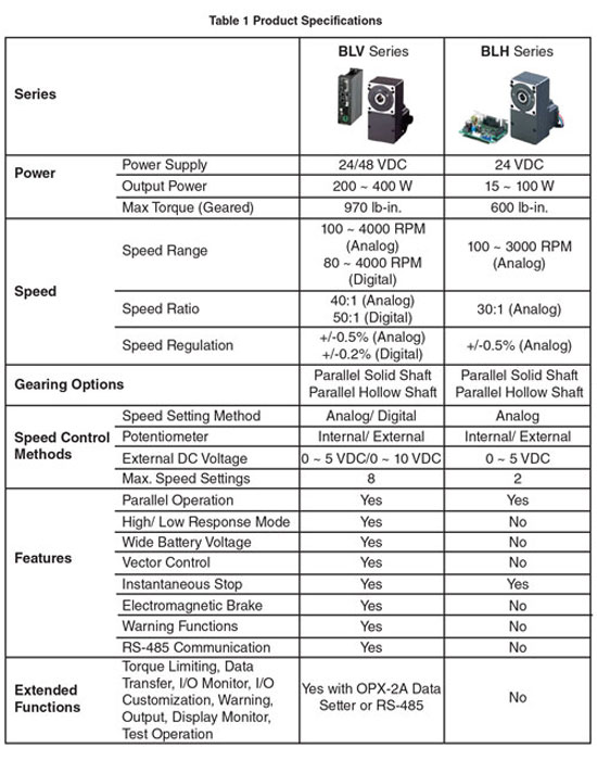
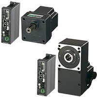
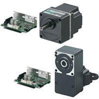
Oriental Motor’s unique advantage of offering preassembled gearmotors, brake, feedback, and dedicated drivers can help reduce product development time and guarantee specifications. The high power BLV series is designed for AGV/AMRs. The compact BLH series is another DC option. While BLH series was designed for general purpose applications, the BLV series was designed with AGV/AMR in mind. To learn more about our 24/48 VDC brushless gearmotor lineup, please refer to the following table below.
For more details regarding AGV/AMR specific functions offered by the BLV series, please read the white paper, “10 Standard Features for AGV/AMR Drivetrain Applications”.