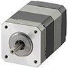
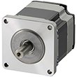
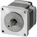
AR Series Hybrid Servo Motor / Stepper Motors
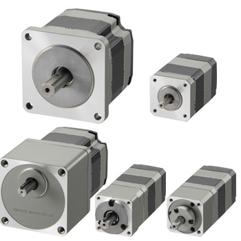
αSTEP Hybrid Step-Servo
AR Series Hybrid Servo Motor / Stepper Motors
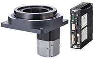
The αSTEP AR Series Hybrid Servo Motor / Stepper Motors offer high efficiency, low vibration, continuous operation with the security of closed loop performance without hunting or gain tuning. Available with a built-in controller or pulse input driver, the system substantially reduces heat generation from the stepper motor through the use of high-efficiency technology. The αSTEP AR Series also achieves up to 40% less power consumption, improved angle accuracy and is capable of driving large inertia loads. For use with αSTEP AR Series Drivers.
- High-Efficiency, Continuous Operation
- Closed Loop Performance, No Hunting or Gain Tuning
- AC or DC Input Types
- Wide Range of Gear Types for Inertia Matching & Higher Torque
- Electromagnetic Brake Types
- αSTEP AR Series Driver Required*
Product Lineup
Frame Size |
Motor Types |
Available Options |
Max. Holding Torque |
|
Standard Type |
Electromagnetic Brake |
42 oz-in |
0.3 N·m |
|
Geared Type |
48 ~ 704 oz-in |
0.35 ~ 5 N·m |
||
Standard Type |
Electromagnetic Brake |
142 ~ 280 oz-in |
1 ~ 2 N·m |
|
Geared Type |
176 ~ 1120 oz-in |
1.25 ~ 8 N·m |
||
|
AC Input |
Standard Type |
Electromagnetic Brake |
280 ~ 560 oz-in |
2 ~ 4 N·m |
Geared Type |
624 ~ 5120 oz-in |
4.5 ~ 37 N·m |
||
* Geared Servo Motor frame size.
αSTEP Closed Loop Performance
High Reliability with Closed Loop Control
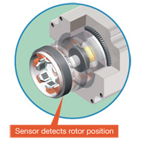
The αSTEP AR Series uses Oriental Motor's closed loop control to maintain positioning operation even during abrupt load fluctuations and accelerations. The rotor position detection sensor monitors the rotation. When an overload condition is detected, the αSTEP AR Series will instantaneously regain control using the closed loop mode. When an overload condition continues, the αSTEP AR Series will output an alarm signal, thereby providing reliability equal to that of a servo motor.
Continuous Operation
The αSTEP AR Series can be operated at high duty cycles allowing the stepper motor to run continuously.
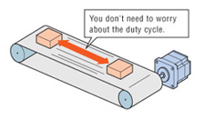
Note: If the stepper motor is operated continuously, a heat sink of a capacity at least equivalent to an aluminum plate with a size of 250 x 250mm*, 6mm thick is required.
*For AC input, 100 x 100mm for DC input type.
Energy-Saving
Power consumption: up to 40% less than our conventional models.
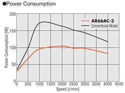
CO2 emission: up to 40% less than our conventional model (assuming operation at a duty of 40%).
Lower Heat Generation
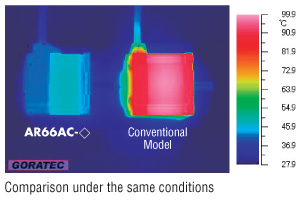
The αSTEP AR Series utilizes high-efficiency technology to achieve a significant reduction in the amount of heat generated from the stepper motor.
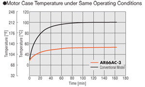
The stepper motor generates significantly less heat than the conventional model as seen in the thermography results below.
The graph below shows the difference in temperature of the stepper motor case over the same period of time under the same operating conditions.
Low Vibration
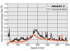
In addition to the microstep drive system, the αSTEP AR Series also uses the smooth drive function to allow for smoother motion. The smooth drive function automatically implements microstep drive based on the same travel amount and speed used in the full-step mode, without changing the pulse input settings.
Improved Angle Accuracy
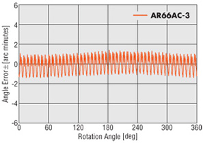
The αSTEP AR Series uses improved current control technology to improve the stop position accuracy of the stepper motor. The result is greater position accuracy.
AR66AC-3: ±3 arc minutes
Conventional Model: ±5 arc minutes
Performance of a Servo Motor
The αSTEP AR Series maintains all of the benefits of a stepper motor.
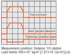
High Response
The stepper motor operates synchronously with pulse commands to achieve high response. There's no delay in operation following a pulse command.
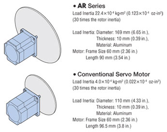
Capable of Driving Large Inertia Loads
Compared to a servo motor of the same frame size, a larger inertial load can be driven regardless of speed conditions.
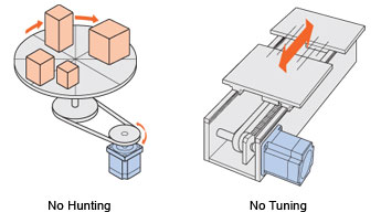
No Hunting / No Tuning
Because it uses a stepper motor, the αSTEP AR Series does not hunt when stopped. Accordingly, the AR Series is ideal for applications where the equipment uses a belt-drive mechanism or otherwise has low rigidity and you don't want it to vibrate when stopping.
With the αSTEP AR Series, you can perform positioning quickly after a load change, etc., without adjusting any gains.
Motor Protection Degree: IP65*
The stepper motor complies with the requirements of protection degree IP65* (except for the motor mounting surface and connectors). This means that the enclosure prevents intrusion of dust that can otherwise inhibit normal operation.
*Excluding 1.10 in. (20 mm) and double shaft models.
Sensorless Homing
The αSTEP AR series features extended functions not normally offered on conventional stepper motors. Using the TLC output on the AR, we can sense a preset torque setting range or perform a torque control function.
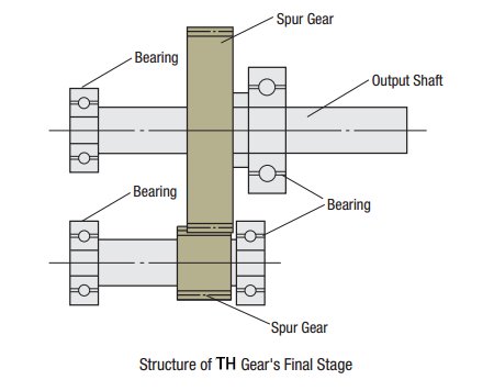
Taper Hobbed Gear Servo Motors (TS)
- 1.65 in. (42 mm)
- 2.36 in. (60 mm)
- 3.54 in. (90 mm)
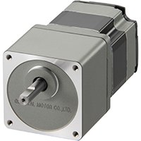
High Speed, Low Backlash Gears
This geared type is made with a simple spur gear design. The torque and speed have been improved.
Because of its high accuracy, this type has the same level of accuracy when compared to our tapered (TH) type without the added cost of tapering.
Planetary Gear Servo Motors (PS)
- 1.65 in. (42 mm)
- 2.36 in. (60 mm)
- 3.54 in. (90 mm)
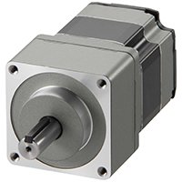
High Permissible Torque, Low Backlash Gears
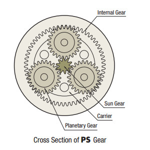
The PS gear mechanism is comprised primarily of a sun gear, planetary gears and an internal tooth gear. The planetary gears design allow for higher output torque.
There are gears inside used to distribute torque, which allows for higher torque than a spur gear design. The PS gear uses a higher accuracy gear design which provides for a lower backlash when compared to a spur gear design.
Planetary Gear Servo Motors (PN)
- 1.65 in. (42 mm)
- 2.36 in. (60 mm)
- 3.54 in. (90 mm)
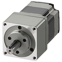
High Permissible Torque, Non-backlash Gears
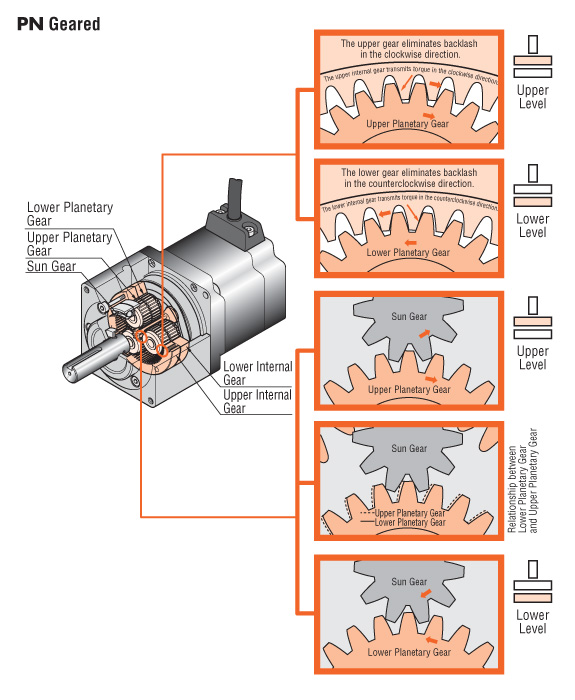
The PN gear employs a planetary gear speed-reduction mechanism. The PN gear achieves the specified backlash of three arc minutes through the improved accuracy of its components and the backlash-elimination mechanism. That mechanism is comprised of two sets of internal and planetary gears on the upper and lower levels with the internal gears and planetary gears reduce clockwise backlash; the lower-level internal gears and planetary gears reduce counterclockwise backlash.
The PN gear mechanism is comprised primarily of a sun gear, planetary gears and an internal tooth gear. The sun gear is installed on the central axis surrounded by planetary gears enclosed in an internal tooth gear centered on the central axis.
Harmonic Gear Servo Motors (HG)
- 1.65 in. (42 mm)
- 2.36 in. (60 mm)
- 3.54 in. (90 mm)
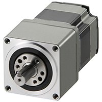
High Accuracy, Non-Backlash Performance Gears
The mechanical life, permissible torque and maximum torque are improved (compared with conventional models).
Improved Rate Life (Twice the length of conventional models)
The rate life has been increased from 5,000 hours (conventional model) to 10,000 hours.
[Except for 1.65 in. (42 mm) frame size]
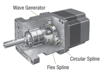
The harmonic gear utilizes the metal’s electrodynamics property. It is comprised of three basic components, a wave generator, flex spline and circular spline.
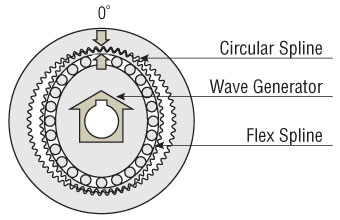
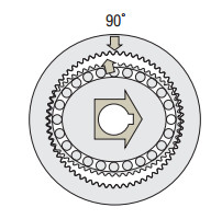
Rotating the wave generator (input) clockwise while keeping the circular spline fixed in position will subject the flax spline to elastic deformation, causing a gradual shift in the point of engagement between the circular spline and flex spline.
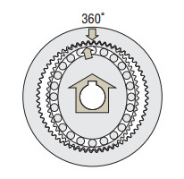
When the wave generator completes one revolution, the flex spline has rotated two fewer teeth than the circular spline has, resulting in the movement of the flex spline for the difference in the tooth count (two teeth) in the opposite direction of the wave generator's rotation (i.e. counterclockwise). This movement translates into output, thereby reducing the speed.
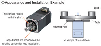
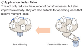
Surface Installation of Load
The harmonic geared type permits installation of load directly on the rotating surface integrated with the shaft. [Expect for geared stepper motors with a frame size of 3.54 in. (90 mm)].
Electromagnetic Brake Option
- 1.65 in. (42 mm)
- 2.36 in. (60 mm)
- 3.35 in. (85 mm) / 3.54 (90 mm)
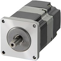
These products have built-in power-off activated electromagnetic brakes. When power is accidentally cut off due to a blackout or other unexpected events, the electromagnetic brake holds the load in position to prevent it from dropping or moving. Also, when the motor is at standstill, it is held by the electromagnetic brake. It is possible to suppress the heat generated from the motor by turning off the motor current.
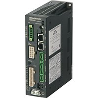
AR Series AC Input Drivers
The αSTEP ARD (AC Input) Drivers offers superior high speed performance, low vibration and closed loop control. Available in a stored data (network) driver or pulse input driver. Advanced operation and function control is included through our MEXE02 software (free download). The αSTEP ARD (AC Input) Drivers can perform quick positioning operations over a short distance without the need for tuning, while providing smooth performance.
- Built-in Protective Functions
- Pulse Input or Built-in Controller (Network) Types
- Single-Phase 100-115, 200-240 VAC or Three-Phase 200-230 VAC
- For use with αSTEP AR Series Motors (AC Input)
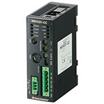
Network Gateways
The communication protocol of the master controller, Factory Automation (FA) network, is converted to Oriental Motor's own RS-485 communication protocol. Connection to Oriental Motor's network compatible products is completed with one RS-485 communication cable.
- Compatible Networks:
CC-Link, MECHATROLINK-II, MECHATROLINK-III, EtherCat
![]()
![]()
![]()
Cables
These cables are used to connect or extend the distance between the motor and driver.
Required (sold separately).
Use a flexible motor cable if the motor is installed on a moving part or its cable will be flexed.
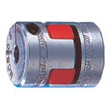
Flexible Couplings
This three-piece coupling adopts an aluminum alloy hub and a resin spider. The simple construction ensures that the high torque generated by a gear motor can be transmitted reliably. The proper elasticity of the spider suppresses motor vibration.
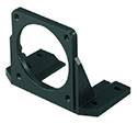
Mounting Brackets
Mounting brackets are convenient for installation and securing a stepper motor or geared stepper motor.
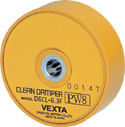
Clean Dampers
Mechanical dampers suppress stepper motor vibration and improve high-speed performance. An inertia body and silicon gel are hermetically sealed in a plastic case.
(For use with Double Shaft motors)
System Configuration
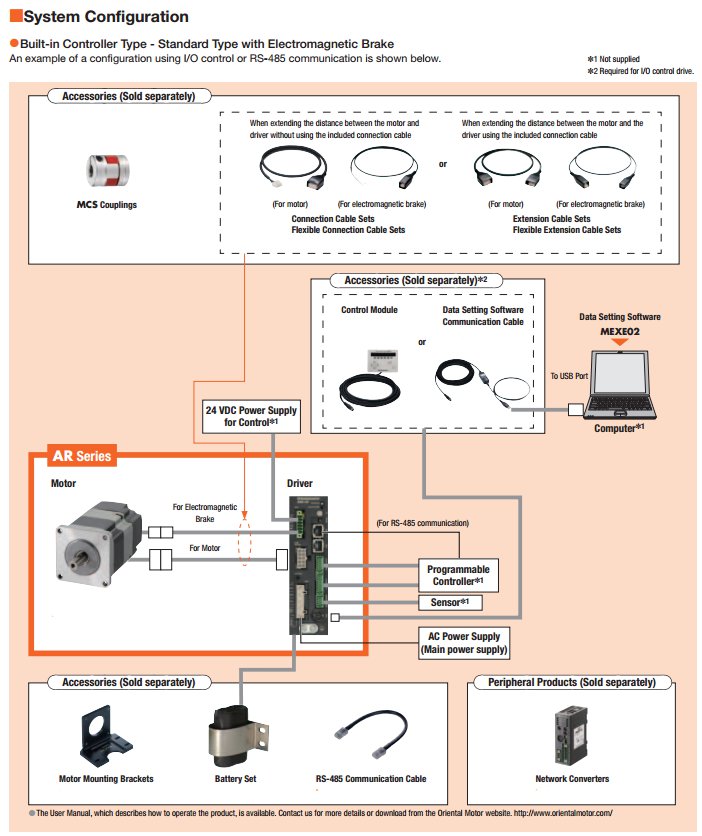
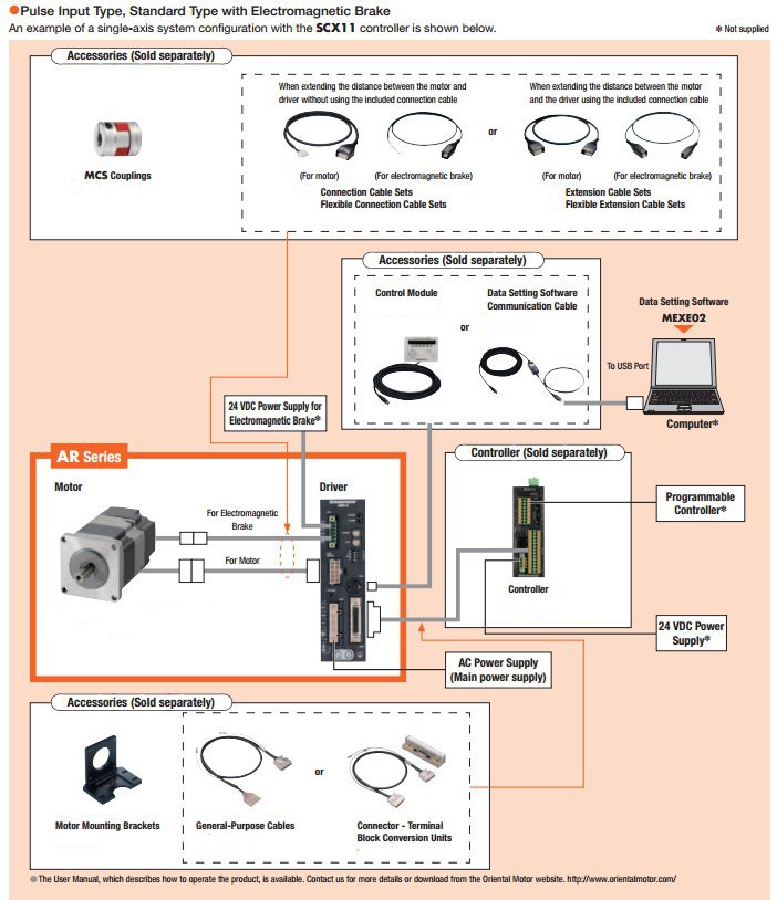
Motor & Driver Combinations
AC Input
|
Built-in Controller (Network) |
Pulse Input |
||||||
Gear |
Rear |
Size |
Motor P/N |
Driver P/N |
Rear |
Size |
Motor P/N |
Driver P/N |
Round |
Single |
46 |
ARM46AC |
ARD-♢D |
Single |
46 |
ARM46AC |
ARD-♢ |
66 |
ARM66AC |
66 |
ARM66AC |
|||||
69 |
ARM69AC |
69 |
ARM69AC |
|||||
98 |
ARM98AC |
98 |
ARM98AC |
|||||
911 |
ARM911AC |
911 |
ARM911AC |
|||||
Double |
46 |
ARM46BC |
Double |
46 |
ARM46BC |
|||
66 |
ARM66BC |
66 |
ARM66BC |
|||||
69 |
ARM69BC |
69 |
ARM69BC |
|||||
98 |
ARM98BC |
98 |
ARM98BC |
|||||
911 |
ARM911BC |
911 |
ARM911BC |
|||||
Electromagnetic |
46 |
ARM46MC |
Electromagnetic |
46 |
ARM46MC |
|||
66 |
ARM66MC |
66 |
ARM66MC |
|||||
69 |
ARM69MC |
69 |
ARM69MC |
|||||
98 |
ARM98MC |
98 |
ARM98MC |
|||||
|
Single |
46 |
ARM46AC |
ARD-S* |
||||
66 |
ARM66AC |
|||||||
69 |
ARM69AC |
|||||||
98 |
ARM98AC |
|||||||
911 |
ARM911AC |
|||||||
Double |
46 |
ARM46BC |
||||||
66 |
ARM66BC |
|||||||
69 |
ARM69BC |
|||||||
98 |
ARM98BC |
|||||||
911 |
ARM911BC |
|||||||
Electromagnetic |
46 |
ARM46MC |
||||||
66 |
ARM66MC |
|||||||
69 |
ARM69MC |
|||||||
98 |
ARM98MC |
|||||||
TH Geared |
Single |
46 |
ARM46AC-T☐ |
ARD-♢D |
Single |
46 |
ARM46AC-T☐ |
ARD-♢ |
66 |
ARM66AC-T☐ |
66 |
ARM66AC-T☐ |
|||||
98 |
ARM98AC-T☐ |
98 |
ARM98AC-T☐ |
|||||
Electromagnetic |
46 |
ARM46MC-T☐ |
Electromagnetic |
46 |
ARM46MC-T☐ |
|||
66 |
ARM66MC-T☐ |
66 |
ARM66MC-T☐ |
|||||
98 |
ARM98MC-T☐ |
98 |
ARM98MC-T☐ |
|||||
|
Single |
46 |
ARM46AC-T☐ |
ARD-S* |
||||
66 |
ARM66AC-T☐ |
|||||||
98 |
ARM98AC-T☐ |
|||||||
Electromagnetic |
46 |
ARM46MC-T☐ |
||||||
66 |
ARM66MC-T☐ |
|||||||
98 |
ARM98MC-T☐ |
|||||||
PS Geared |
Single |
46 |
ARM46AC-PS☐ |
ARD-♢D |
Single |
46 |
ARM46AC-PS☐ |
ARD-♢ |
66 |
ARM66AC-PS☐ |
66 |
ARM66AC-PS☐ |
|||||
98 |
ARM98AC-PS☐ |
98 |
ARM98AC-PS☐ |
|||||
Electromagnetic |
46 |
ARM46MC-PS☐ |
Electromagnetic |
46 |
ARM46MC-PS☐ |
|||
66 |
ARM66MC-PS☐ |
66 |
ARM66MC-PS☐ |
|||||
98 |
ARM98MC-PS☐ |
98 |
ARM98MC-PS☐ |
|||||
|
Single |
46 |
ARM46AC-PS☐ |
ARD-S* |
||||
66 |
ARM66AC-PS☐ |
|||||||
98 |
ARM98AC-PS☐ |
|||||||
Electromagnetic |
46 |
ARM46MC-PS☐ |
||||||
66 |
ARM66MC-PS☐ |
|||||||
98 |
ARM98MC-PS☐ |
|||||||
PN Geared |
Single |
46 |
ARM46AC-N☐ |
ARD-♢D |
Single |
46 |
ARM46AC-N☐ |
ARD-♢ |
66 |
ARM66AC-N☐ |
66 |
ARM66AC-N☐ |
|||||
98 |
ARM98AC-N☐ |
98 |
ARM98AC-N☐ |
|||||
Electromagnetic |
46 |
ARM46MC-N☐ |
Electromagnetic |
46 |
ARM46MC-N☐ |
|||
66 |
ARM66MC-N☐ |
66 |
ARM66MC-N☐ |
|||||
98 |
ARM98MC-N☐ |
98 |
ARM98MC-N☐ |
|||||
|
Single |
46 |
ARM46AC-N☐ |
ARD-S* |
||||
66 |
ARM66AC-N☐ |
|||||||
98 |
ARM98AC-N☐ |
|||||||
Electromagnetic |
46 |
ARM46MC-N☐ |
||||||
66 |
ARM66MC-N☐ |
|||||||
98 |
ARM98MC-N☐ |
|||||||
Harmonic |
Single |
46 |
ARM46AC-H☐ |
ARD-♢D |
Single |
46 |
ARM46AC-H☐ |
ARD-♢ |
66 |
ARM66AC-H☐ |
66 |
ARM66AC-H☐ |
|||||
98 |
ARM98AC-H☐ |
98 |
ARM98AC-H☐ |
|||||
Electromagnetic |
46 |
ARM46MC-H☐ |
Electromagnetic |
46 |
ARM46MC-H☐ |
|||
66 |
ARM66MC-H☐ |
66 |
ARM66MC-H☐ |
|||||
98 |
ARM98MC-H☐ |
98 |
ARM98MC-H☐ |
|||||
|
Single |
46 |
ARM46AC-H☐ |
ARD-S* |
||||
66 |
ARM66AC-H☐ |
|||||||
98 |
ARM98AC-H☐ |
|||||||
Electromagnetic |
46 |
ARM46MC-H☐ |
||||||
66 |
ARM66MC-H☐ |
|||||||
98 |
ARM98MC-H☐ |
|||||||
♢ = A (Single 100-120 VAC) / C (Single 200-240VAC)
*S = Three Phase 200-240V
☐ = Gear Ratio
CAD / Manual Search
To locate product CAD and Operator Manuals please search using the product Item Number.
