Brushless DC Motors (BLDC Motors) & Gear Motors > AC Input Brushless DC Motor Speed Control Systems > BLE2 Series Brushless DC Motors (BLDC Motors) (AC Input)
BLE2 Series Brushless DC Motors (AC Input)
BLE2 Series Brushless DC Motors (BLDC Motors) & Gear Motors (AC Input)
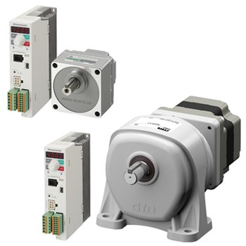
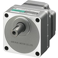
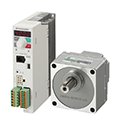
The BLE2 Series features a compact, high-power and high-efficiency brushless DC motor. The entire motor structure features our latest brushless DC motor technology and has been innovated in pursuit of the optimal performance. It is combined with a Driver that can be digitally set and controlled via external DC voltage or by the front panel.
The BLE2 Series has a maximum speed of 4000 r/min. Speed ratio of 1:50 (80 to 4000 r/min) is achieved. Featuring 30 W (1/25 HP), 60 W (1/12 HP), 120 W (1/6 HP), 200 W (1/4 HP), 300 W (2/5 HP) and 400 W (1/2 HP) output power models.
- Speed Control Range: 80 ~ 4000 r/min
- Advanced Performance and Features with Easy to Use Controls
- Torque Limit Function
- Parallel Shaft, Right-Angle Hollow Shaft Gear, Hollow Shaft Flat Gear or Round Shaft (no Gear)
- H1 Food-Grade Grease-Compatible gear motors available.
- Electromagnetic Brake Type Available
- IP65, IP66 and Stainless Steel IP67/IP69K Types (for Hollow Shaft Flat Gearhead) Available
- Imperial or Metric Shafts Available
Features of Brushless DC Motors
Brushless DC motors are more efficient and compact than AC induction motors and do not use brushes as compared to DC Brush motors. Brushless DC motors allow for quiet, long life maintenance-free operation. Brushless motors include permanent magnets in the motor’s rotor providing high power and high efficiency and built-in hall effect IC in the stator for speed detection. Speed is controlled through a driver by using feedback signals from the motor.
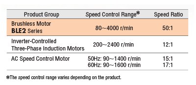
Wide Speed Control
Brushless DC motors have a broader speed control compared to
three-phase AC inverter driven motors. Additionally they are ideal
for applications that require constant torque from low to high
speed.
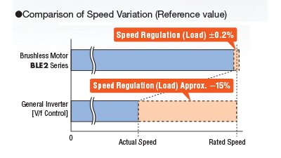
Stable Speed Control
The driver constantly monitors feedback signals from the motor and
then adjusts the applied voltage by comparing the signals against the
set speed. For this reason, even if the load changes, stable rotation is
performed from low speed to high speed.
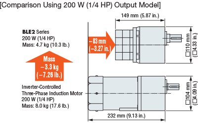
Slim, Light, High Power
Brushless DC motors have a slim body and provide high power due
to permanent magnets being used in the rotor. This contributes
to downsizing of equipment.
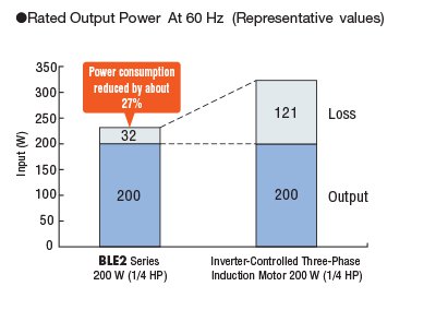
Contributes to Energy Savings
Brushless DC motors significantly reduce power consumption as the use
of permanent magnets in the rotor prevents secondary loss from the
rotor, which provides a large decrease in power consumption. This
helps the equipment save energy.
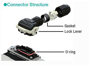
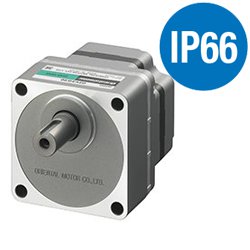
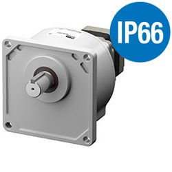
Degree of Protection IP66
The connector is newly developed for small motors and enables a direct connection between the motor and driver. Connecting is easy due to the lock lever that does not require screws. Also, the motor structure has achieved an IP66* degree of protection for its improved watertight and dust-resistant performance. The internal gasket and O-ring improve the watertight performance.
*The degree of protection and output shaft material vary depending on the types of gearheads combined. See the product lineup for details.
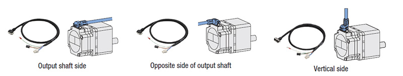
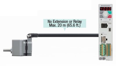
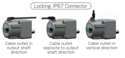
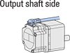
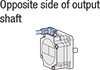
Selectable Cable Outlet Direction
Three types of the connection cables are available, depending on which direction the cable will be drawn. Since a single connection cable can connect directly between the driver and motor at a distance of up to 20 m (65.6 ft.), no extension cable is required.
Only One Connection Cable is Needed
Because only one cable is required for the power line, signal line and ground wire, wiring work can be reduced.
Electromagnetic Brake
Electromagnetic Brake Models Available for Vertical Drive
The motor with an electromagnetic brake enables stable speed control even during vertical drive (gravitational operation). When the power is turned off, the motor stops instantaneously to hold the load in place. The electromagnetic brake is automatically controlled via the driver in accordance with ON/OFF of the operation command signal.
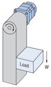
* Since regenerative energy is produced during vertical operation, a regeneration unit (sold separately) is required.
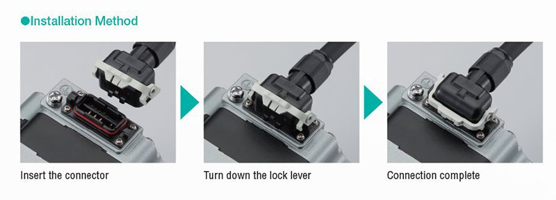
Easy Setting, Installation and Wiring
The new motor structure is smaller than previous versions and enables high power and high efficiency. The driver is equipped with a digital display that allows the speed to be set via a single potentiometer. Additionally, connection cables now allow for a choice of cable outlet direction with direct connection (one cable) providing a maximum distance of up to 20 m (65.6 ft.).
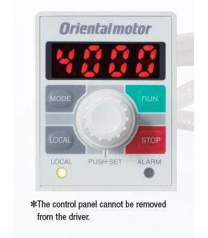
The Control Panel Allows for Easy Setting
The operating data and parameters can be set by using the operation keys or the dial while checking the digital display.
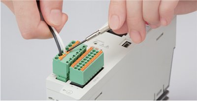
Quick and Accurate Wiring and Connection
Quick and reliable wiring is possible thanks to the use of spring type connectors.
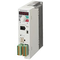
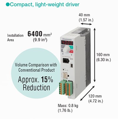
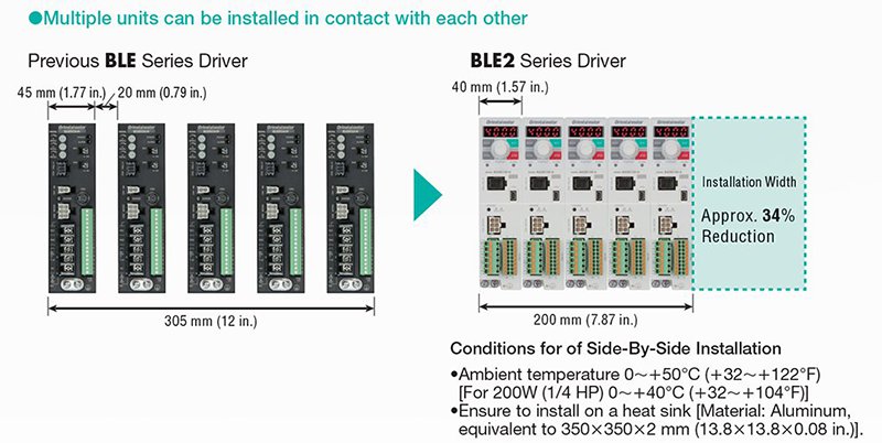
Effective Utilization of Installation Space
The driver has a compact and slim body through the rearrangement of the internal components to optimize space. Multiple drivers can now be installed in contact with each other, making it possible to reduce the amount of installation space or increase the number of axes within the same equipment space.
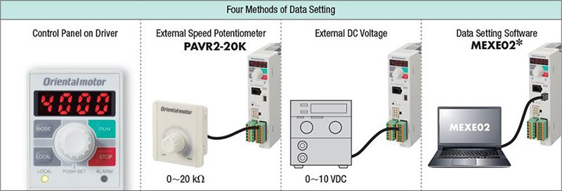
Supporting Customers with Enhanced Functions
The driver is equipped with four methods of data setting and various functions that correspond with your purpose of use. By using data setting software, equipment start-up and checking operating status is simple. Functions are provided in accordance with the customer' usage conditions.
Operating Method
Major Useful Functions
This section introduces the main functions available when using the driver's control panel and the data setting software MEXE02.
Application and Purpose |
Function |
Description |
Check the motor generated torque. |
Load factor indication |
With the rated torque of the motor at 100%, load factor is displayed. (Indication range: 0∼300%) |
Display conveyor transportation speed or speed reduction in a gearhead. |
Gear Ratio |
When the gear ratio is set, the converted rotation speed can be displayed. |
Operate the motor within the specified speed control range. |
Sets upper and lower speed limits |
Specify the upper and lower speed limit. |
Change the motor speed while the motor is rotating. |
Speed Teaching |
In monitoring mode, the rotation speed can be changed while the motor is rotating. |
Easily hold the motor in position when it is stopped. |
Simple Holding Torque |
When the motor is stopped, the load can be electrically held. (Holding force up to 50% of rated torque) Note: Since the holding force is canceled when the power supply to the driver is turned OFF, it cannot be used to prevent falling during standstill. |
Alleviate shock when starting and stopping. |
Impact Softening Filter |
This function offers slow acceleration and stopping, so that the load being transported during starting and stopping does not move. |
Check problem details. |
Alarm |
This function enables you to identify and quickly respond to problems, including an overload, a disconnection or an operation error. |
Use for operation verification and regular maintenance. |
General Information |
Output prior to the output of an alarm. Inputting the appropriate values for each of the information parameters is also useful for equipment maintenance. |
Protect the specified data. |
Editing lock |
Prohibits the editing/deletion of data and parameters using the driver's control panel and local operation. |
Useful Functions of Data Setting Software MEXE02
Monitoring Function
This software is equipped with various monitoring functions for checking the operating status of the motor. Using the functions in accordance with the situation reduces the time necessary for equipment start-up and adjustment, and facilitates effective maintenance.
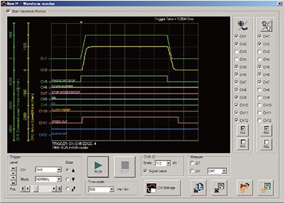
Waveform Monitoring
The operating status of the motor and output signals can be monitored like an oscilloscope. This can be used for equipment start-up and adjustment.
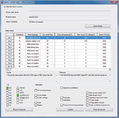
Alarm Monitoring
When an abnormality occurs, the details of the abnormality, the operating status at the time of the occurrence, and the solution can be checked. Because the solution can be checked, it is possible to respond to abnormalities quickly.
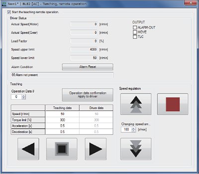
Test Function
This function allows the motor to operate by itself and to confirm connection with the host system. Using this function at equipment startup leads to shortening the time needed.
Speed Adjustment
Prior to connection to the host system, the speed data can be changed during testing. These changed speed settings can be saved and used, helping to reduce set-up time.
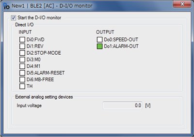
I/O Monitoring
This allows for testing of the input/output signals used for direct I/O. This allows the monitoring of input signals and external DC voltage values, as well as forced output of the output signals. This functions is useful when checking wiring and connections to the host system.
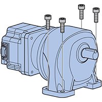
Long-Life, Parallel Shaft Gearhead (IP66)
- 30 W (1/25 HP)
- 60 W (1/12 HP)
- 120 W (1/6 HP)
- 200 W (1/4 HP)
- 300 W (2/5 HP)
- 400 W (1/2 HP)
High-Strength Gearhead
High strength is achieved through improving the strength of gears through heat treatment and through larger bearing diameters. The high permissible torque is 2 ~ 3 times that of a gearhead for an AC motor with the same frame size, and this contributes to reducing the size of equipment.
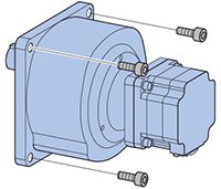
New Gearhead (combination type)
With the gearhead's boss and machined mounting surface, the installation accuracy has been greatly improved. The new gearhead also has lower audible noise as compared to our previous type and comes pre-assembled (motor and gear) as a combination type.
Long Life
A long life gearhead that uses a special bearing and grease for high speed rotation.
A rated life of 10000 hours is achieved.
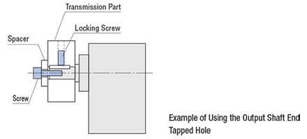
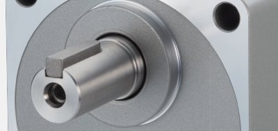
Tapped Hole at the End of the Output Shaft (GFV Gear 80 mm (3.15 in.) min.)
A tapped hole has been machined at the tip of the output shaft. This can be used as an aid for preventing transmission parts from coming off.
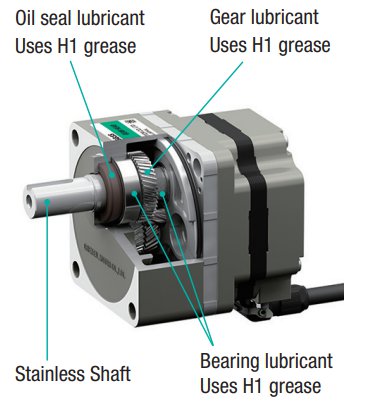
Standardized Use of Stainless Steel Shaft
These brushless DC IP66 motors include a shaft made of SUS303 type steel, which provides excellent rust prevention and corrosion resistance. Stainless steel is also used in the parallel keys and installation screws.
H1 Food-Grade Grease-Compatible (IP66)
- 30 W (1/19 HP)
- 60 W (1/12 HP)
- 100 W (1/8 HP)
H1 Food-Grade Grease-Compatible Gearhead
The gearhead uses the NSF registered H1 food-grade lubricant (grease).
What is H1 Food-Grade Grease?
It is a grease registered by the NSF as part of a category where the "lubricants used in food-processing environments where there is the possibility of incidental food contact."
What is NSF International?
NSF is an American-based international, third-party certification body which provides global services such as development of standard, product certification, auditing, training and risk management for the public health and environmental sectors.
Watertight, Dust-Resistant Parallel Shaft (IP67)
- 200 W (1/4 HP)
- 300 W (2/5 HP)
- 400 W (1/2 HP)
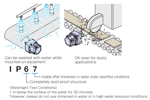
Watertight, dust-resistant brushless motors that withstand wet and dusty environments and can be washed with water.
Degree of Protection IP67
Can be used in dusty and wet environments. Can be washed with water.
Designed to be mounted on equipment as-is with no protective cover.
Rust Resistant
The motor is covered with a special rust-resistant coating, with an output shaft and screws made of stainless steel. The installation surface is also painted, so it will be rust-resistant even when installed in stainless steel equipment.
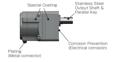
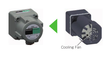
Suited for Clean Environments
The motor is highly efficient, so it has no cooling fan.
Easy Equipment Design
3 cable outlet directions can be selected, increasing the freedom of equipment design. Enables relay-free, direct connection between the motor and driver.
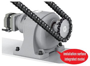
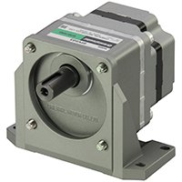
Parallel Shaft (Foot Mount Type) - JB Gear (IP44)
- 200 W (1/4 HP)
- 300 W (2/5 HP)
- 400 W (1/2 HP)
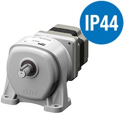
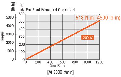
Foot Mount Gearhead JB Gear
The gear ratio is 1/1200 with maximum allowable torque of 518 N•m. Torque is not saturated with the new gearhead, therefore, maximum output torque is available at each gear ratio.
No Mounting Bracket Needed
Configured so it can be quickly installed on equipment.
High Rigidity / Internal Structure
Well designed shaft axis, integrated construction with installation surface.
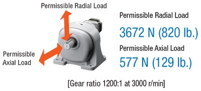
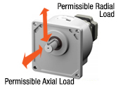
High Permissible Torque
High permissible radial and axial load strength enables powerful, high-spec operations.
Superior Mechanical Strength
High permissible radial and axial load strength enables powerful, high-spec operations.
IP66 Parallel Shaft Type - JV Gear
- 200 W (1/4 HP)
- 300 W (2/5 HP)
- 400 W (1/2 HP)
Superior Mechanical Strength
High permissible radial and axial load strength enables powerful, high-spec operations.
- Stainless Steel Shaft
Can Be Installed on the Flange Surface
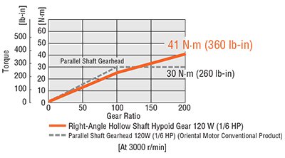
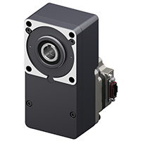
IP66 Right-Angle Hollow Shaft - JH Gear
- 60 W (1/12 HP)
- 120 W (1/6 HP)
- 200 W (1/4 HP)
- 300 W (2/5 HP)
- 400 W (1/2 HP)
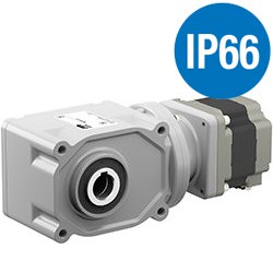
High Allowable Torque
Torque is not saturated with the new right-angle hollow shaft Hypoid JH gear, therefore, maximum output torque is available at each gear ratio.
- Stainless Steel Shaft
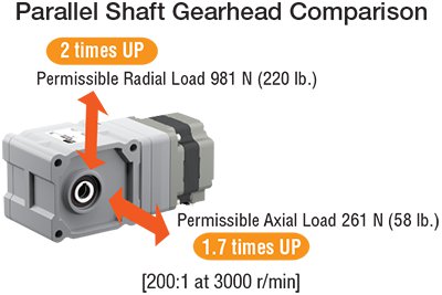
Superior Mechanical Strength
High permissible radial and axial load strength enables powerful, high-spec operations.
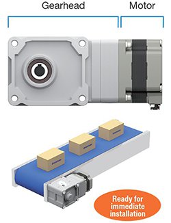
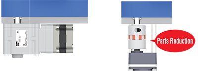
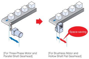
Pre-Assembled Motor & Gearhead
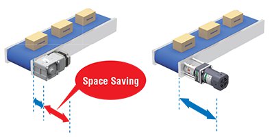
Space Saving
Space reduction is achieved when mounted along side the conveyor belt. Because the output shaft of the gear is vertically in the middle of the installation surface, it is possible to change the installation direction horizontally, tailored to equipment position of installation.
Low Cost
Component cost saving is achieved through reduction of fastening parts, assembly steps reduced through mechanism simplification. Maintenance cost is also reduced or eliminated as a result.
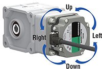
Flexible Installation
The gearhead can be removed and the assembly position can be changed in 90˚ increments. The connector positions can also be changed to suit the equipment.
Hollow Shaft Flat Gearhead - FR Gear (IP65)
- 30 W (1/25 HP)
- 60 W (1/12 HP)
- 120 W (1/6 HP)
- 200 W (1/4 HP)
- 300 W (2/5 HP)
- 400 W (1/2 HP)
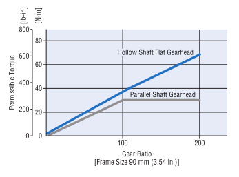
Permissible Torque without Saturation
The hollow shaft flat gearhead enables permissible torque without saturation even at high gear ratios. The motor torque can be fully utilized.
Low Cost
By eliminating parts such as a coupling or belt-and-pulley, the parts cost and labor will also decrease.
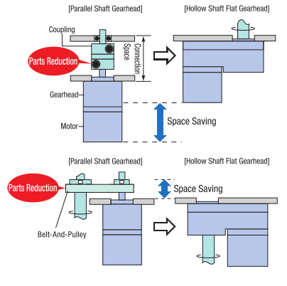
Space Saving is Achieved with a Hollow Shaft Flat Gearhead
The output shaft can be coupled directly to your drive shaft without using a coupling. The flexible installation modes, such as installation on either the front or rear face or by using the center shaft, allows you to reduce the size and installation space of your equipment. Since no shaft-coupling parts are needed, the parts cost and assembly man-hours will also decrease.
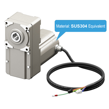
Stainless Steel IP67/IP69K
- 200 W (1/4 HP)
The stainless steel type brushless DC motor is rated for IP67, which indicates the level of dust and water protection class specified under the IEC 60529 and IEC 60034-5 standards. It is also rated for IP69K, which indicates the level of dust and water protection class specified under the DIN 4005-9 standard.
This motor is made of stainless steel equivalent to SUS304, which provides excellent corrosion resistance. As it is not painted, the paint will not peel off.

IP Code Definitions
Dustproof |
Waterproof |
|
IP |
6 |
9K |
Dustproof
Grade |
6 |
Completely dustproof construction: |
|---|
Watertight
Grade |
7 |
Usable even when submerged under the following conditions: |
|---|---|---|
9K |
Protected against high-temperature, high-pressure, powerful water jets. |
Brushless DC Motor (BLDC Motor) & Gear Motor Lineup
Output Power |
Gear Options |
Options |
Power Supply |
Rated Torque |
Speed Range |
|
|
Parallel Shaft or |
Electromagnetic Brake |
Single-Phase 100-120 VAC |
4.7 ~ 53 lb-in |
0.54 ~ 6 N·m |
80 ~ 4000 r/min Min: 0.4 [200:1] |
Hollow Shaft Flat Gear |
3.5 ~ 150 lb-in |
0.4 ~ 17 N·m |
||||
Round Shaft (no Gear) |
13.6 oz-in |
0.096 N·m |
||||
|
Parallel Shaft or |
Electromagnetic Brake |
Single-Phase 100-120 VAC |
7.9 ~ 141 lb-in |
0.9 ~ 16 N·m |
80 ~ 4000 r/min Min: 0.4 [200:1] |
Right-Angle Hollow Shaft (Stainless Steel)* |
10.6 ~ 182 lb-in |
1.2 ~ 20.6 N·m |
||||
Hollow Shaft Flat Gear |
7.5 ~ 300 lb-in |
0.85 ~ 34 N·m |
||||
Round Shaft (no Gear) |
27 oz-in |
0.191 N·m |
||||
|
Parallel Shaft or |
Electromagnetic Brake | Single-Phase 100-120 VAC |
17.6 ~ 260 lb-in |
2 ~ 30 N·m |
80 ~ 4000 r/min Min: 0.07 [1200:1] |
Right-Angle Hollow Shaft* |
28 ~ 470 lb-in |
3.2 ~ 53.9 N·m |
||||
Hollow Shaft Flat Gear |
16 ~ 680 lb-in |
1.9 ~ 77 N·m |
||||
Round Shaft (no Gear) |
54 oz-in |
0.382 N·m |
||||
|
Parallel Shaft |
Electromagnetic Brake | Single-Phase 100-120 VAC |
25 ~ 610 lb-in |
2.9 ~ 70 N·m |
80 ~ 4000 r/min Min: 0.19 [600:1] |
Parallel Shaft (Foot Mount)* |
21 ~ 4500 lb-in |
2.4 ~ 518 N·m |
||||
Parallel Shaft - JV* |
1160 ~ 1750 lb-in |
132 ~ 198 N·m |
||||
Right-Angle Hollow Shaft* |
18.5 ~ 730 lb-in |
2.1 ~ 82.8 N·m |
||||
Hollow Shaft Flat Gear |
47 ~ 470 lb-in |
5.4 ~ 54 N·m |
||||
Round Shaft (no Gear) |
90 oz-in |
0.637 N·m |
||||
|
Parallel Shaft |
- | Single/Three-Phase 200-240 VAC |
38 ~ 610 lb-in |
4.3 ~ 70 N·m |
80 ~ 4000 r/min Min: 0.19 [600:1] |
Parallel Shaft (Foot Mount)* |
31 ~ 3400 lb-in |
3.6 ~ 388 N·m |
||||
Parallel Shaft - JV* |
1210 ~ 2600 lb-in |
137 ~ 297 N·m |
||||
Right-Angle Hollow Shaft* |
29 ~ 1180 lb-in |
3.3 ~ 134 N·m |
||||
Hollow Shaft Flat Gear |
71 ~ 710 lb-in |
8.1 ~ 81 N·m |
||||
Round Shaft (no Gear) |
135 oz-in |
0.955 N·m |
||||
Parallel Shaft |
- | Single-Phase 200-240 VAC |
50.4 ~ 483.2 lb-in |
5.7 ~ 54.6 N·m |
80 ~ 4000 r/min Min: 0.19 [600:1] |
|
Parallel Shaft (Foot Mount)* |
47.79 ~ 5159 lb-in |
5.4 ~ 583 N·m |
||||
Parallel Shaft (Stainless Steel Shaft)* |
955.8 ~ 3814 lb-in |
108 ~ 431 N·m |
||||
Right-Angle Hollow Shaft (Stainless Steel)* |
42.48 ~ 1575 lb-in |
4.8 ~ 178 N·m |
||||
Hollow Shaft Flat Gear |
46 ~ 940 lb-in |
5.3 ~ 107 N·m |
||||
Round Shaft (no Gear) |
180 oz-in |
1.27 N·m |
||||
*Maximum input speed for Gearhead limited to 3600 r/min.
**Parallel Shaft only.
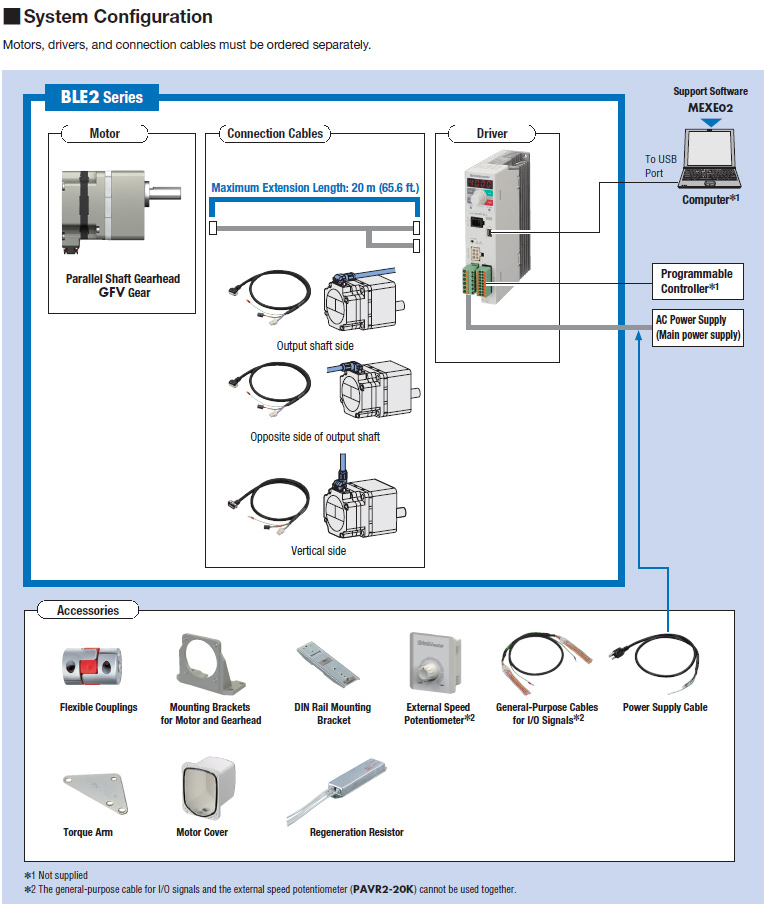
Connection / Extension Cables (required)
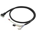
These cables are required to connect the motor and driver. Use a flexible motor cable if the motor is installed on a moving part or its cable will be flexed.
Power Supply Cables
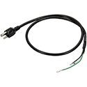
Power Supply cable for the BLE2 Series.
General-Purpose Cables for I/O Signals
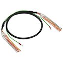
A cable for connecting the driver and programmable controller.
External Speed Potentiometer
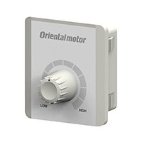
A potentiometer that can adjust speed and torque.
DIN Rail Mounting Brackets
Use DIN rail mounting brackets to install a driver to a DIN rail.
Rotary Encoders
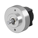
Small, thin, and lightweight stand-alone rotary encoders with an outer diameter of ϕ30 mm can be installed in tight spaces.
Flexible Couplings
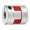
These products are clamp type couplings used to connect a motor or gearhead shaft to the shaft of the equipment.
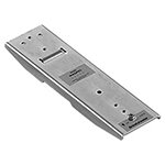
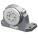
Mounting Bracket
This is an aluminum die cast mounting bracket for geared motors.
Long, horizontal holes make it easy to make fine adjustments during installation.
Flange Drive Adapter
Permissible load has been increased by mounting with a parallel shaft gearhead. Direct mounting of the rotation mechanism to wheels or rotary tables has been simplified, which helps reduce design time.
*For use with 120W Parallel Shaft Gear Motors (Metric Shaft)
IP66 Motor Cover
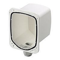
This cover protects the motor. They are compatible with the degree of protection IP66 specification and can be used in wet and dusty environments.
Output |
Motor |
Direction of Cable Outlet |
30 W (1/25 HP) |
Parallel Shaft Gearhead - GFV Gear |
|
Round Shaft (no Gear) |
|
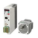
System Configuration
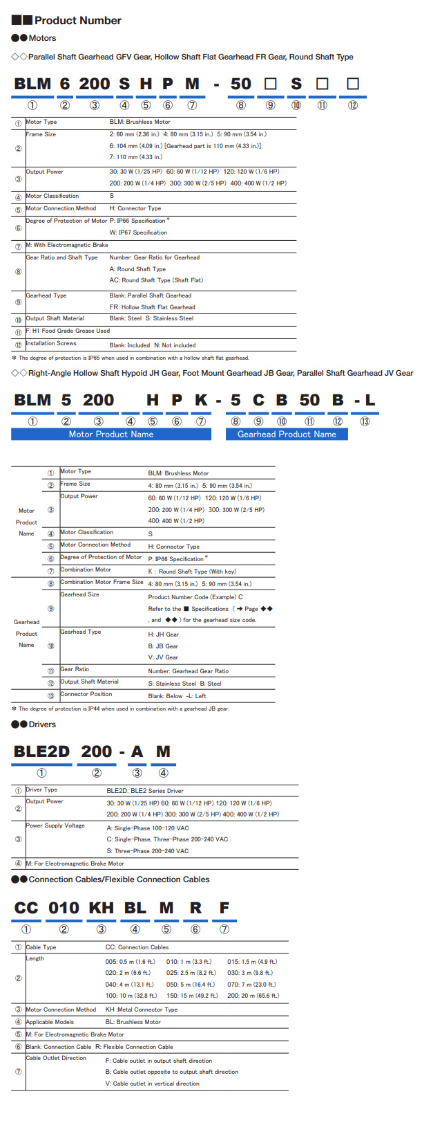
Part Number Code
CAD / Manual Search
To locate product CAD and Operator Manuals please search using the product Item Number.
Videos
Technical Articles
Reference
Videos


Rotary Encoders

Product Brochure
