Brushless DC Motors > Technology > Contribution to Carbon Neutrality Using Brushless Motors
Contribution to Carbon Neutrality Using Brushless Motors
The Paris Agreement, adopted at the 2015 United Nations Climate Change Conference (COP21), sets a goal of “limiting the increase in the global average temperature to well below 2 degrees Celsius above pre-industrial levels while pursuing efforts to limit it to 1.5 degrees”(1). Countries around the world are engaged in activities to achieve carbon neutrality by the second half of this century. To achieve carbon neutrality, it is essential to reduce energy consumption along with the use of clean energy and the reuse of CO2 emitted. Looking at global energy consumption, since motors account for 53% (2), replacing the motors currently in use with high-efficiency motors will lead to reduction in global energy consumption and the achievement of carbon neutrality. This report explains the reduction effect of energy consumption for the high-efficiency brushless motor among various motors.
1. Introduction
To achieve the goal of limiting the increase in the global average temperature to 2 degrees Celsius while striving for 1.5 degrees, all parties have created a reduction target of greenhouse gas and engaged in activities to reduce energy consumption. To reach carbon neutrality in 2050, Japan set a target of reducing greenhouse gas emissions by 46 % by 2030 from 2013 levels(3). In the “Sustainable Development Goals (SDGs)” adopted at COP21, Goals 1, 2, 11, and 13 include the mitigation of risks posed by climate change(4) (see Figure 1).

Activities to prevent global warming are required on a global scale, and carbon neutrality is essential to achieving the goal. In order to achieve carbon neutrality in the industrial field, it is necessary to use renewable energy with low CO2 emissions, to store and reuse CO2, and to reduce CO2 emissions by reducing energy consumption. Focusing on the reduction of energy consumption in particular, motors account for 53 % of global energy consumption (see Figure 2), and replacing them with high-efficiency motors leads directly to carbon neutrality.
Many countries have introduced energy-efficiency regulations for electrical equipment, and motors are also subject to regulation because they account for more than half of global energy consumption. Motors used in continuous operation, such as compressors, pumps, and fan motors, account for 70 % of the total energy consumption of motors, and the scope of regulations is expanding from the present induction motors to include synchronous motors(5) (6).
This report compares induction motors and brushless motors (synchronous motors) sold by Oriental Motor, and explains how to contribute to carbon neutrality in addition to the reduction effect of energy consumption by using brushless motors.
2. Structure, Drive System, and Loss for Each Motor
2.1. Induction Motors
2.1.1. Motor Structure
Figure 3 shows the structure of an induction motor. A stator has windings (coils) of copper wire inserted into a core of laminated electrical steel sheets, and the passage of alternating current through the windings creates a rotating magnetic field. A rotor consists of a core of laminated electrical steel sheets and a squirrel cage conductor (aluminum) (see Figure 4). The rotating magnetic field of the stator and the induced current of the rotor generated by the rotating magnetic field of the stator interact to rotate the rotor. This induced current creates secondary copper losses, which are the major factor in reducing efficiency (see Figure 5).
In addition, since magnetic flux must be generated in both the stator and the rotor, the electrical power required to rotate an induction motor is greater than that of a brushless motor described below. As a result, the efficiency deteriorates especially in the low-speed, low-torque operating range.
2.1.2. Variable-Speed Drive of Induction Motors
There are two methods of variable-speed control for driving induction motors, inverter control and phase control. Inverter control is a method of controlling the motor speed by changing the voltage and frequency applied to the motor and is used for three-phase induction motors. Phase control is a method of controlling the motor speed by changing only the voltage applied to the motor. It is used for single-phase induction motors with a tachogenerator and is used in conjunction with closed-loop control. (7)
2.2. Brushless Motors
2.2.1. Motor Structure and Drive System
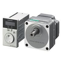
Figure 6 shows the structure of a brushless motor. Windings are wound around the stator, and permanent magnets are fixed on the rotor surface. Hall ICs are installed as sensors to detect the position of the rotor, and closed loop control is performed by controlling the current to the stator windings based on the position and speed information of the rotor (see Figure 7). A drive circuit (driver) controls the current flowing through the stator windings to create a rotating magnetic field in the stator, thereby rotating the rotor. There is no induced current through the rotor and no secondary copper loss in the rotor as in an induction motor because a brushless motor uses permanent magnets for the rotor. Using permanent magnets makes the electrical power required to rotate a brushless motor less than that of an induction motor, resulting in lower losses (see Figure 8). In addition, the accuracy of detecting the rotor poles is improved by surface mounting the hall ICs used for the sensor, and the technology of controlling the motor current in the driver is further developed, enabling a high-efficiency drive. In recent years, further improvements in efficiency have been achieved by using low-loss electrical steel sheets, increasing the winding area by optimizing the stator shape, and using thicker electrical wires. (8)
3. Efficiency Comparison of Each Motor
3.1. Efficiency Measurement Method
A method to measure efficiency is by reading the indication of a power meter when a constant load is applied to the motor by a torque load device and the input power to the equipment at each operating point (see Figure 9). Based on this measured value, the efficiency is calculated by the formula below.
3.2. Comparison of Power Consumption at the Same Output Power
The following example shows a comparison of power consumption when driving an induction motor with a rated output power of 90 W and when driving a brushless motor under operating conditions where the output power becomes 90 W (see Table 1). It indicates that the power consumption of a brushless motor is lower when the motor output power is equal.
3.3. Comparison by Efficiency Maps
When a motor is operated with variable speed drive, efficiency must be compared over the entire operating range since it changes according to the load factor and rotation speed. Therefore, an efficiency map showing the efficiency at each operating point within a range of continuous operation is often used. Figure 10 shows a comparison of the the efficiency maps of the induction motor and brushless motor described in Table 1.
In this example, the load factor for the induction motor is the ratio of the load torque to the rated torque when the rated torque is 100 % at 60 Hz. The load factor for the brushless motor is the ratio of the load torque to the rated torque when the rated torque is 100 % (see Figures 11 and 12). It shows that the brushless motor is more efficient over a wider range.
4. Comparison of Power Consumption Using Conveyor as an Example
4.1. Power Consumption at Constant Speed Drive
Power consumption is compared when a gearhead is assembled with an induction motor and brushless motor described in Table 1 to drive a conveyor at a constant speed (see Table 4). Table 2 shows the torque and rotation speed of the gearhead output shaft, and Table 3 shows the operating conditions of the equipment.
A comparison under the above conditions shows that using the brushless motor reduces power consumption and CO2 emissions by 37 % per year.
The efficiency of a geared motor is reduced compared to a motor by itself because of losses caused by the internal load of the gearhead. Transmission efficiency represents a ratio (%) of the output power from a motor and that from a gearhead output shaft through gears (see Table 5). It varies depending on the gear type or the gear ratio due to structural differences, such as the number of gear stages. In the case of a geared motor, it is necessary to calculate the load factor of the motor output shaft, taking into account the transmission efficiency of the gearhead.
4.2. Effect on Power Consumption due to Rotation Speed Change
Based on the conveyor drive described in 4.1, this section compares power consumption when a load is repeated to transport at 100 r/min and to decelerate to 30 r/min for inspection (see Table 6). The operating time at high-speed and low-speed is 50 % each and the total operating time is the same as that in Table 3.
A comparison of power consumption under these conditions shows that both power consumption and CO2 emissions are reduced by 69% per year with a brushless motor (see Table 7). Compared to the constant speed drive described in section 4.1, the difference in efficiency between the induction motor and the brushless motor becomes greater. This is because the efficiency of the brushless motor is slightly reduced, while that of the induction motor is greatly reduced by changing the operating point (see Figure 13). As a result, the brushless motor can operate with higher efficiency even in applications where speed and torque vary.
5. Comparison of Motor Size and Mass
Changing from an induction motor to a brushless motor can reduce the motor size and mass (see Figure 14). Although the frame size is the same, the total length of the motor and gearhead for the induction motor is 200 mm, while that of the brushless motor is 95.4 mm, or 104.6 mm shorter.
The mass of the induction motor is 4.7 kg, while that of the brushless motor including the motor and driver is 3.1 kg, which is 1.6 kg lighter, even including the driver. Therefore, a brushless motor contributes to downsizing of equipment, reducing CO2 emissions during transportation, and waste.
6. Improvement in Efficiency of Fans by Brushless Motor
High-efficiency fans using brushless motors are also available (see Figures 15 and 16). Compared to conventional models that use an induction motor, it is possible to significantly reduce power consumption (see Table 8). In addition, since it is possible to change the speed using external analog settings or PWM signals, adjusting the airflow based on a load of equipment in the control panel can reduce not only power consumption, but also noise (see Table 9).
7. Summary
Our brushless motors are high-efficiency motors that contributes to carbon neutrality, and we explained the effects of reducing energy consumption. A brushless motor is higher in efficiency than an induction motor and can significantly reduce energy consumption and CO2 emissions.
Oriental Motor will continue to accurately assess society's needs and develop products and services to meet those needs.
References
(1) United Nations “Report of the Conference of the Parties on its twenty-first session”, (2015), p.4
(2) IEA “World Energy Outlook 2016”, (2016), pp.297-298
(3) Ministry of Economy, Trade and Industry, “The 6th Strategic Energy Plan”, (2021), p.4
(4) Oriental Motor Co., Ltd., Naoto SHOYAMA, “Latest Status of Energy Efficiency Regulations for Induction Motors and Fan Motors”, RENGA No. 2110, (2021)
(5) CEL 038-2020 Implementation Rules for Energy Effi ciency Labeling of Permanent Magnet Synchronous Motors
(6) IEA “Walking the Torque: Proposed Work Plan for Energy-Effi ciency Policy Opportunities for Electric Motor-Driven Systems ”, (2011), p.15
(7) Oriental Motor Co., Ltd., Masahiro TAKIMOTO, “Feature and control technology of the MSC-1 speed controller”, RENGA No. 176, (2012), pp.14-20
(8) Oriental Motor Co., Ltd., Shinya KUWATA, Ayuka HORI, “Features of the NexBL BMU Series Brushless Motor and Driver Package”, RENGA No. 179, (2014), pp.5-8
Brushless DC Gear Motors
Brushless DC Gear Motors