Brushless DC Motors & Gear Motors > Technology > Industrial Network Communications Flex
New Concept of Industrial Network Communications and Introduction of FLEX Products
In order to meet various requirements, Programmable Logic Controllers (PLCs) and motors/drivers in equipment have been connected in numerous ways, such as pulse train, digital I/O, and fieldbus networks.
We have developed products that can be connected to multiple industrial networks. They can be connected to an I/O device and Modbus RTU network. They can also be connected to other field bus networks through a Network Converter (our gateway product). The products can be flexibly connected to a host PLC and it allow customers to select a system depending on their needs. We call this concept FLEX. Since some of the FLEX products have a positioning function, positioning units of host PLCs can be omitted and costs of equipment can be reduced. The FLEX products allow customers to reduce costs and time of developing equipment by using each merit of industrial networks.
We introduce the merits of each control system and the FLEX products by using the keywords "cost reduction" and "shortening equipment launch time".
1. Introduction
There are various demands and needs regarding production equipment, such as cost reduction, shortened launch time for new equipment, productivity improvement, energy saving, and traceability. Over the last few years, there has been a strong need for cost reduction. However, it is never a good idea to impair equipment performance just to achieve reducing equipment costs because it jeopardizes our competitiveness. In order to compete against low cost equipment manufacturers, it has become important to focus on "cost performance" that lowers cost while maintaining equipment performance, rather than focusing on the mere "cost reduction" aspect. Also, it is essential to bring machines to market as early as possible, in order to gain an upper hand on competitors. This demand has become even tougher in recent years. This article introduces FLEX Industrial Network Communications products that respond to demands such as "cost reduction" and "shortened equipment launch time".
2. What is FLEX
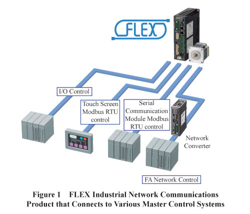
FLEX is the general term for Industrial Network Communications products supporting; (1) I/O control, (2) Modbus RTU control (Note 1) and (3) Factory Automation (FA) network control via a network converter. Oriental Motor offers FLEX as a system that can be selected freely based on a user's needs and be flexibly connected with various host controllers. FLEX Industrial Network Communications products are compatible with these three control methods (Refer to Figure 1).
(1) I/O Control - Because I/O control enables a motor to move easily with ON/OFF signals only, it leads to "shortened equipment launch time". Also, a simple input/output device is used for the master control system and therefore, it can be built with the the "lowest cost".
(2) Modbus RTU control - Modbus RTU control is a type of serial communication control (Refer to Section 4.2). Serial communications are strong against noise, and a communication line can be extended up to 50m (164.04 ft.) (Note 2), resulting in "cost reduction". There are many master control systems that are compatible with serial communications and can be selected freely without being bound by manufacturers in the same manner as the I/O controls. Also, because most touch screens are equipped with Modbus communications as a standard, it is easy to operate from a touch screen.
The ability to select manufacturers freely (expanding the possibility of equipment design) and being able to operate from a touch screen easily leads to "shortened time to launch a new equipment".
(Note 1) Modbus is a registered trademark of Modbus-IDA.
(Note 2) The maximum extension length of 50m (164.04 ft.) is the specification for Oriental Motor's products which are compatible with Modbus.
(3) Factory Automation (FA) Network Control via Network Converter - Factory Automation (FA) network control via a network converter is available with products that can be connected with CC-Link, MECHATROLINK- II / III, or Ether CAT. Because FA network requires less wiring, as the number of motors increases, "cost reduction" becomes more evident. FA network automatically transmits and receives data via a dedicated communication IC. Therefore, a motor can be operated in the sense as the I/O control. This also leads to "shortened time to launch new equipment".
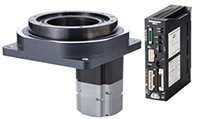
Accordingly, FLEX products connect to various kinds of master control systems because of compatibility with the Industrial Network Communications, and thus fully utilize the advantages of each product. Stepper motors and hollow rotary actuators featuring positioning control, and brushless motors featuring speed control are available as part of FLEX's product lines (Refer to Figure 2). By using FLEX products, motors with different purposes of operation can be connected with the same control (connection) method.

3. Built-in Controller (Stored Data) Type
3.1. What Is Built-in Controller (Stored Data) Type?
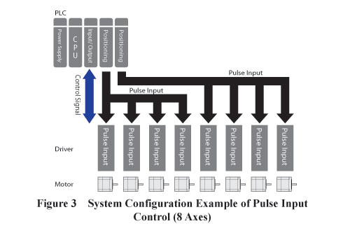
Along with a motor and driver (amplifier), positioning control motors epitomized by servo motors and stepper motors require a pulse generator, which is also called a positioning module or controller for PLC (Refer to Figure 3).
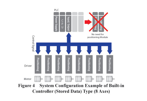
For Oriental Motor's FLEX Industrial Network Connections product lines, particularly the positioning control stepper motors, drivers are equipped with the pulse generator, and thus the pulse generator (positioning module for PLC) can be eliminated from master control systems. This results in "overall cost reduction" of the equipment (Refer to Figure 4).
Also, the built-in pulse generator in the driver is not a mere pulse generator, but it also has various functions that can be utilized for the positioning control. Various positioning functions are introduced in the next chapter.
3.2. Various Functions of Built-in Controller (Stored Data) Type
3.2.1. Operating Function that Can Set Stopping Time
There is a function called the "linked operation 2", which is suitable for a simple back-and-forth operation, that allows presetting the traveling amount and speed. It simplifies the starting signal with a single ON switch (Refer to Figure 5).
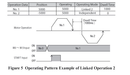
The "linked operation 2" function allows the stopping time (dwell time) to be set from operation to operation via a driver. Therefore, a simple back-and-forth operation can be conducted with a single starting signal. This is suitable for an application that brings the load back to the original position automatically at work completion, for example. With this function, the PLC programming creation load (design man-hour) can be eliminated.
3.2.2. Operating Function that Sequentially Executes Positioning Operation
For applications such as conveyor and stocker transportation, which require regular feed (pitch feed), a function called the "sequential positioning operation" is convenient. The "sequential positioning operation" is a function that executes operating data numbers in sequence every time the starting signal turns on.
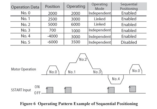
By presetting the values, such as the traveling amount, speed and operating functions, and repeating the starting signal ON/OFF (ON/OFF of I/O signals), various kinds of operating patterns can be executed. In addition, most of the functions for the PLC positioning module, such as the return-to-home operation and continuous operation (speed-change operation while switching operating data), are built into the driver.
3.2.3. Function for Unlimited Operations in the Same Direction
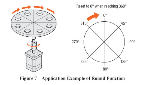
When a motor continuously operates in the same direction in the rotational mechanism, and it reaches the maximum value of the command position, the value changes to the minimum. When the command position circulates like this, it becomes very hard to control the motor position. This problem can be solved by automatically resetting the motor position information to zero at any given point within one rotation or multiple rotations. Oriental Motor calls this function the "round function". This can be used for applications such as an index table and turn table (Refer to Figure 7).
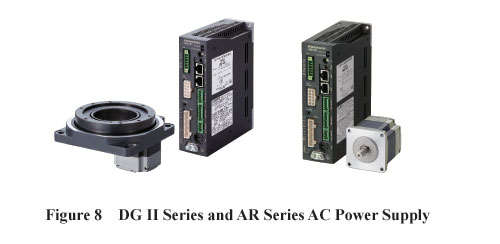
Also, by combining the round function and the absolute system, which retains and stores the motor position information with the battery backup system, the "operating system of unlimited multiple rotations" can be built with the non-return-to-home operation. This round function is installed on the AR Series FLEX built-in controller type and the hollow rotary actuator DG II Series FLEX built-in controller type (Refer to Figure 8).
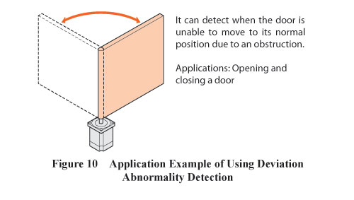
3.2.4. Deviation Abnormality Detection Function (Encoder Type Motor)
The deviation abnormality detection function is available for the 0.72°/0.36° stepper motor and driver package CRK Series FLEX built-in controller type. By using an encoder type motor, it is easier to detect abnormalities such as a positional error of the motor (Refer to Figure 9 and 10).
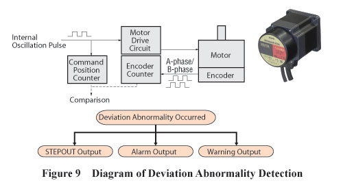
Because it only requires an encoder to be connected to a driver, it is unnecessary to add devices such as a counter module to the host PLC. Therefore, it not only detects a deviation abnormality at a low cost, but also eliminates the programming labor for the host PLC to calculate the deviation abnormality, resulting in shorter equipment launch time.
The built-in controller (stored data) type is equipped with the function of a positioning module for the PLC, along with the function as described above. Accordingly, it does not require a positioning module for the PLC, making it easier for users to control the objective performance.
4. Various Control Methods of FLEX
4.1. I/O Control
The I/O control monitors the motor using the I/O signal terminals on the front of the driver (Refer to Figure 11).
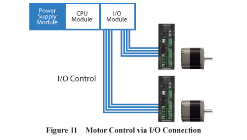
Because the I/O control directly turns the I/O signals on and off, it has the least lag among the Industrial Network Communications methods. For the equipment with a tight takt time, either this I/O control or the pulse input control is suitable.
Also, a motor is easily controlled with a simple ON/OFF of the I/O signals with the relay control and therefore, the PLC programming can be done easily, contributing to a shorter equipment launch time. For simple equipment, a motor can be operated with an external switch and without a host PLC, reducing cost.
On the other hand, disadvantages of the I/O control are that multiple wires are required and operating data (traveling amount and speed) cannot be rewritten freely. Therefore, the I/O control is limited to applications that operating patterns are predetermined per load. These disadvantages can be resolved with the Modbus RTU control and the Factory Automation (FA) network control via a network converter.
4.2. Modbus RTU Control
Modbus is a serial communication protocol (communication procedure) primarily used with a PLC and was developed by Modicon Inc. (AEG Schneider Automation International S.A.S). Its protocol specifications have been published across the globe. It has been used in many industrial fields such as a bar code reader, RFID (IC tag, etc.), displacement sensor, load cell, thermal regulator and vision sensor (camera). Many devices, such as an inverter, are now compatible with Modbus. In order to use the Modbus control with a host PLC, a serial communication module is required (Refer to Figure 12).
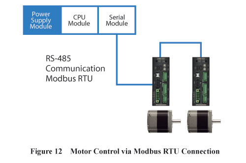
In regard to touch screens, most manufacturers install the Modbus communication protocol as standard and therefore, it is easy to communicate once the serial communication method is set with Modbus RTU. As described above, Modbus has various kinds of connection devices. Because Oriental Motor's products are capable of connecting up to 31 axes to one Modbus master controller, cost reduction is possible as a positioning module for the PLC is not required. What the Modbus control is capable of is, that in addition to starting and stopping the motor, operating data, such as the traveling amount and speed, can be rewritten freely, which the I/O control cannot do. Parameters, such as running current, can also be changed. Furthermore, it is capable of obtaining various kinds of information such as alarm codes, and it is also capable of monitoring positioning information of a motor.
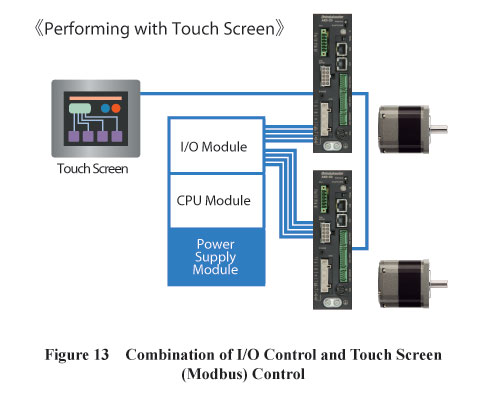
These advantages are applied to not only the Modbus control, but also the Factory Automation (FA) network control via a network converter, which will be discussed in the following section. The following is an application example of combining the I/O control and Modbus control (Refer to Figure 13). In general, a motor is driven by the I/O control and touch screens are used when the traveling amount and speed need to be changed (during model change, etc.).
This configuration is achieved with the "lowest cost" and reduces the design man-hour for PLC programming. Also, it takes about 10ms to start the I/O control, thus takt time can be shortened.
For the inverter control, the speed command via analog voltage or analog volume used to be the mainstream method, but the digital control via Modbus communication has become more popular recently (Refer to Figure 14).
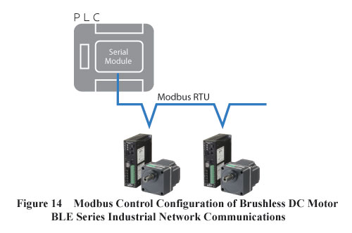
Contrary to the analog control, advantages of the digital control via Modbus communication are that the digital control is strong against noise and is capable of extending the wiring length. Oriental Motor's speed control motor, brushless BLE Series, is compatible with the Modbus RTU control.
4.3. Factory Automation (FA) Network Control (via Network Converter)
There are several leading protocols of the Factory Automation (FA) network control, such as DeviceNet, CC-Link, MECHATROLINK, SSCNET, Modbus and CANopen. Recently, other network controls, such as Ethernet based EtherCAT, EtherNet/IP, PROFINET and CC-Link/IE, have started to gain popularity. A network converter is a protocol converting device that converts FA network's protocol into Modbus (RT)/ RS-485 protocol in order to control FLEX Industrial Network Communications products under various FA networks (Refer to Figure 15).
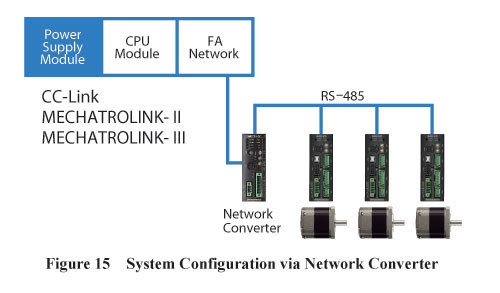
In terms of the network converter, various converter products are available from Oriental Motor that are compatible with Ether-CAT, CC-Link, MECHATROLINK- II and MECHATROLINK- III, in order to meet demands for network.
In other words, without modifying mechanism designs or diagrams for products, such as a driver and motor located below the network converter, this enables it to be compatible with various kinds of FA Industrial Network Communications, reducing design man-hour. By employing a network converter, it is possible to easily achieve equipment variations that are compatible with every network.
Because the network converter is compatible with a wide variety of networks, it requires much less wiring, whereas the I/O control requires wiring of multiple I/O signals. Not only is wiring made simpler, but wiring labor and mistakes are reduced. In terms of effectiveness and cost, its advantageous effect gets greater as the number of motors increases.
The network converter via FA network not only starts and stops motors, but also sets parameter and operating data, such as the traveling amount and speed, monitors positioning information of motors, and obtains alarm codes. From the standpoint of the host PLC, it looks as if motors and drivers are connected to the FA network directly and therefore, it is unnecessary to recognize the RS-485 communication control located under the network converter. Furthermore, starting and stopping of motors is controlled as with the I/O control, thus PLC programming can remain very simple.
5. Network Converter
From the standpoint of the FA network (Master) of the host PLC, there is only one network converter. Because more than 10 drivers can be connected beneath the network converter, the maximum number of connectible motors becomes more than that of the FA network specifications. Therefore, it is unnecessary to add another host master, resulting in cost saving. The network converter is the product that allows for equipment to "reduce overall cost".
5.1. Structure of Network Converter
In order for one network converter to control multiple motors, the network converter secures the memory range (Refer to Figure 16).
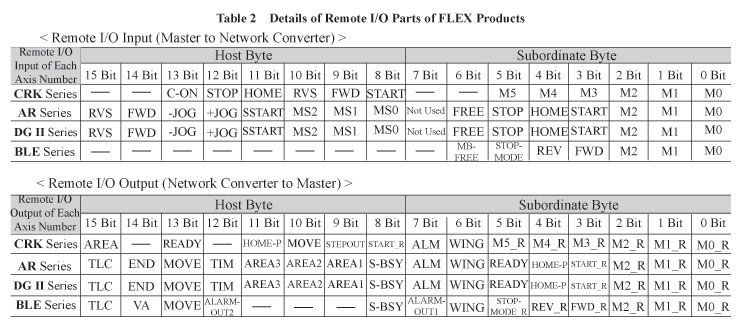
The memory range largely consists of two groups; one is the "remote I/O" which is used for motor control, and the other is the "remote register" which reads and writes operating data (traveling amount and speed) and parameters. The remote I/O has all of the driver's I/O information beneath the network converter. Its purpose is to reduce the overall system cost by controlling multiple motors at once with the remote I/O, without increasing the number of host masters.
As Table 2 indicates, the remote I/O plays a central role in starting and stopping of motors, and this concept is inherited from a network with a simple ON/OFF signal of the I/O to control motors easily. The network converter performs RS-485 communication while distributing signals to a driver from the smallest axis number, and in ascending order at regular intervals per driver (this is called polling). Communication is done in the order corresponding to the number (1) to (12) (as shown in Figure 16).
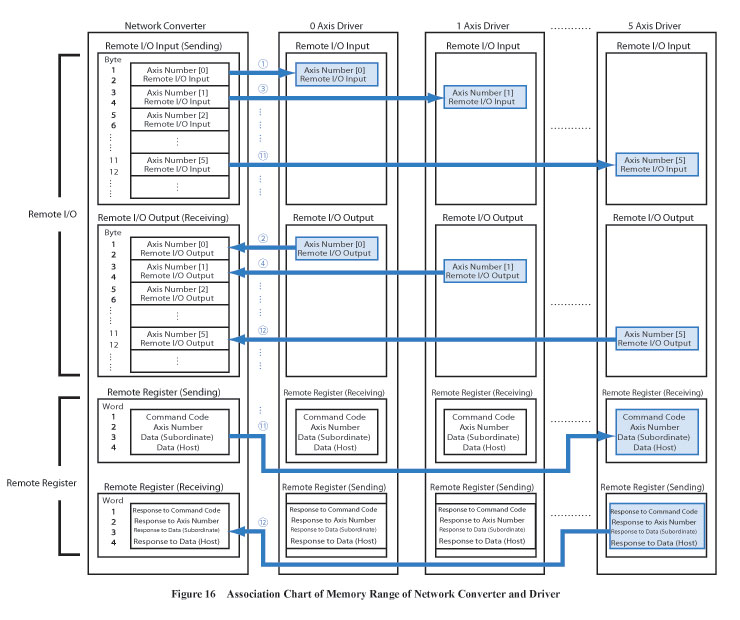
Because polling is done at all drivers, the remote I/O, which is involved in motor control, has the up-to-the-minute information at all times. On the other hand, the remote register, which reads and writes data, has adopted a method that accesses a designated axis number only. Figure 16 is an example that the remote register accesses only 5 axis driver (Refer to (11) and (12) in Figure 16).
5.2. Communication Time Delay of Network Converter
Because the network converter performs communication with drivers at a constant frequency per driver (1ms cycle), the more the number of connected drivers increase, the longer RS-485 communication time delay gets.
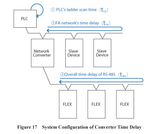
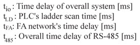
As shown in Figure 17, communication delay is largely classified into three factors; (1) PLC's ladder scan time (tLD), (2) FA network's time delay (tFA), and (3) Overall time delay of RS-485 (t485).
The time delay of the overall system (tio) is obtained by the formula below. The delay of the overall system denotes the starting time delay via the remote I/O. For example, it is the time delay until a motor starts moving from the moment when the START signal from the host master turns on.
![]()
In regard to (3) Overall time delay of RS-485, it becomes greater in proportion to the number of connected drivers, due to the fact that polling is done approximately 1ms cycle per driver. Also, because both (2) and (3) are asynchronous communications, (3)'s RS-485 communication cycle requires up to 2 cycles. Therefore, ③Overall time delay of RS-485 is obtained by the formula (2).
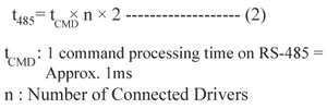
Accordingly, the time delay of the overall system is obtained by the equation (1) and (2), which is (3).
![]()
With the formula (3), the following example explains the case using a CC-Link converter: Let's assume that only one network converter is connected to a CC-Link communication line, and (2) FA network's time delay (CC-Link communication's time delay) is approximately 4ms round trip, while tLD (PLC's ladder scan time) is 1ms. Figure 18 shows the calculation results with the formula (3).
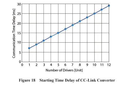
According to Figure 18, when simultaneously turning on the starting signal from PLC for the connected 12 units, the motors start moving after approximately 30ms later. What needs to be noted is that the starting signal, which was sent from the host PLC and received at the converter, is distributed via RS-485 communication. Therefore, 12 motors begin to operate in the order of lowest to highest axis number with a minimum of 1ms delay (possible to delay at a maximum of 2 cycles).
Since there are remote I/Os for all axes, the motor control when starting the motors can be obtained from formula (3).
However, because there is only one remote register per unit for data transfer, such as a traveling amount change, it is necessary to transfer data for as many drivers as connected in order to rewrite the traveling amount for multiple drivers.
The following concept explains the data transfer time delay which occurs at the time of the data transfer:
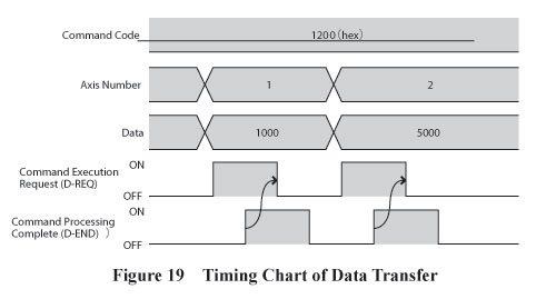
For data transfer, such as a traveling amount change, the command execution request (D-REQ) is turned on to start the execution, after setting a command code, axis number, and data in the remote register.
Data transfer is changed per unit, thus it is necessary to turn off the command execution request (D-REQ) before changing the data for the next unit. Turning off the command execution request (D-REQ) is done via PLC programming, while ensuring that the command processing complete (D-END) is turned on (Refer to Figure 19).
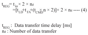
Therefore, the command execution request (D-REQ) needs to be turned on and off in order to transfer single data. Accordingly, the data transfer time delay can be obtained with the formula (4).
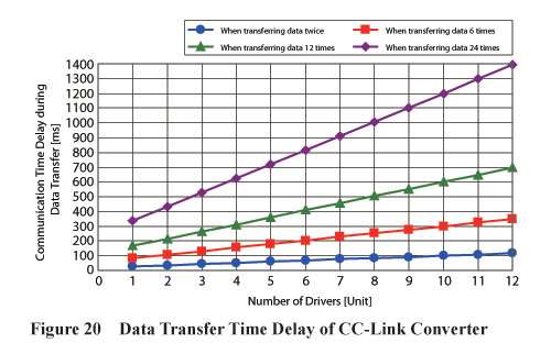
According to Figure 20, if there are 6 units connected to each driver, for example, the data transfer time delay is approximately 400ms when rewriting the traveling amount and speed (total number of data transfer is 12 times).
6. Summary
The use of FLEX Industrial Network Communications contributes to "cost reduction" of the overall equipment and "short equipment launch time". Also, FLEX is compatible with common control methods and therefore, a suitable control method can be freely selected based on a user's needs. In other words, it can connect devices flexibly without being bound by the host system, thus it leads to an increased range of equipment design options. Among the FLEX product lines, stepper motors, linear actuators, hollow rotary actuators and brushless DC motors are available and these motors can be "connected" with the same connection condition. In order to be compatible with diversified FA networks even further, Oriental Motor will continue to expand the network converter product lines as well as the FLEX product lines including, actuators and servo motors of linear products.
Reference Literature
Modbus-IDA website, Modbus-IDA, http://www.- modbus.org/, (2012/4/19)CC-Link Association website, CC-Link Association, http://www. cc-link.org/jp/, (2012/4/19) MECHATROLINK Association website, MECHATROLINKAssociation, http://www.mechatrolink.org/jp/, (2012/4/19) ODVA website, ODVA (Open DeviceNet Vender Association), http://www.odva.org/, (2012/5/6) Mitsubishi Electric Corporation website, SSCNET III, http://www.mitsubishielectric.co.jp/fa/products/ cnt/ssc/catalog/sscnet/index_j.html, (2012/5/6) CiA website, CiA (CAN in Automation), CANopen, http://www.can-cia.org/, (2012/5/6) EtherCAT Technology Group (ETG) website, EtherCAT, http://www.ethercat.org/jp.htm, (2012/5/6) Japanese PROFIBUS Organization website, PROFINET http://www.profibus.jp/index.htm, (2012/5/6) CC-Link is a registered trademark of CC-Link Association (CLPA: CC-Link Partner Association). MECHATROLINK- II / III is a registered trademark of MECHATROLINK Association (MMA: MECHATROLINK Members Association). Device Net, EtherNet/IP are registered trademarks of ODVA (ODVA: Open DeviceNet Vender Association). SSCNET is a registered trademark of Mitsubishi Electric Corporation. CANopen is a registered trademark of CiA (CiA: CAN in Automation). EtherCAT is a registered trademark of ETG (ETG: EtherCAT Technology Group). PROFINET is a registered trademark of PI (PI: PROFIBUS & PROFINET International). CC-Link/IE is a registered trademark of CC-Link (CLPA: CC-Link Partner Association).
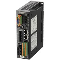
Stepper Motor Drivers
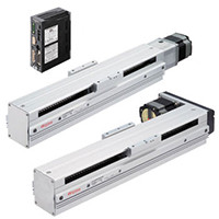
Linear Actuators
Hollow Rotary Actuators