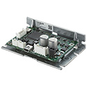
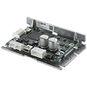
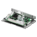
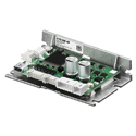
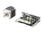
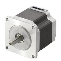
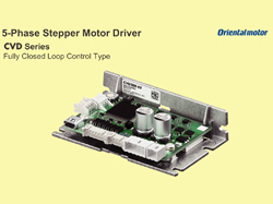
CVD 5-Phase Stepper Motor Drivers (DC Input)
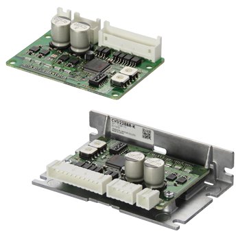
CVD 5-Phase Stepper Motor Drivers
The CVD 5-phase stepper motor driver offers superior performance and value and is ideal for OEM or single axis machines. The CVD stepper motor drivers offer:
- Lowest Vibration and Noise with advanced Microstepping control
- Pulse Input, RS-485 Communications, Fully Closed-Loop, Speed Control or Multi-Axis Type
- Significantly improves positional accuracy when microstepping
- Small, thin microstepping drive with space saving FETs
- Selectable step angle and microstepping filter control
- Various mounting types and connector configurations
- Alarms
- 24 VDC Input
Stepper Motor Driver Lineup
Stepper Motor Drivers |
Driver |
Current |
Motor Types |
Power Supply |
|
|---|---|---|---|---|---|
|
0.35 A/Phase |
5-Phase |
24 VDC |
||
0.75 A/Phase |
|||||
1.2 A/Phase |
|||||
1.4 A/Phase |
|||||
1.8 A/Phase |
|||||
2.4 A/Phase |
|||||
2.8 A/Phase |
|||||
3.8 A/Phase |
|||||
|
0.35 A/Phase |
5-Phase |
24 VDC |
||
0.75 A/Phase |
|||||
1.2 A/Phase |
|||||
1.4 A/Phase |
|||||
1.8 A/Phase |
|||||
2.4 A/Phase |
|||||
|
0.35 ~ 2.4 A/Phase |
5-Phase |
24 VDC |
||
|
0.35 ~ 2.4 A/Phase |
5-Phase |
24 VDC |
||
|
0.35 ~ 2.4 A/Phase |
5-Phase |
24 VDC |
||
|
0.35 ~ 2.4 A/Phase |
5-Phase |
24 VDC |
||
Board Mounting Type |
I/O Setting |
0.35 ~ 2.4 A/Phase |
5-Phase |
24 VDC |
|
SPI Communication |
|||||
Board Mounting Type |
I/O Setting |
0.35 ~ 2.4 A/Phase |
5-Phase |
24 VDC |
|
SPI Communication |
|||||
Multi-Axis Drivers - Board Type
|
0.5 ~ 3.0 A per axis. (Max. 12 A) |
2-Phase 5-Phase |
24 VDC |
||
Multi-Axis Drivers - Board Type Right Angle Connectors
|
0.5 ~ 3.0 A per axis. (Max. 12 A) |
2-Phase 5-Phase |
24 VDC |
||
Speed Control (SC) Type |
- |
5-Phase |
24 VDC |
||
Wide Product Line of Compact Microstepper Drivers to Suit Any Application
The CVD Series is a compact line of stepper motor drivers capable of handling a wide variety of applications. When used with the PKP Series Stepper Motors, the CVD Series offer the lowest vibration and noise with advanced microstepping control and the highest torque output.

Features of the CVD Series
The CVD Series drivers developed exclusively for the PKP Series stepper motors enables increased performance and functionality.
Industry's Top Compact, High Performance Driver
These compact and lightweight drivers contribute to saving space. The 2-phase and 5-phase drivers are identical in size, installation and I/O connectors. This allows for the selection and evaluation of 2-phase or 5-phase drivers based on the required specifications.
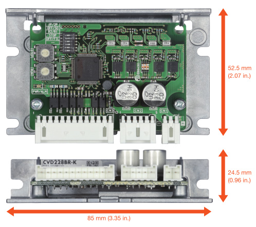
Select Drivers by Mounting Method
Drivers with different shapes and connector locations are available to match the mounting method.

High-Efficiency Design
The CVD Series provides increased torque by increasing the output current compared to conventional products. In order to allow the increase of output current, the design incorporates measures to reduce the amount of heat generated.

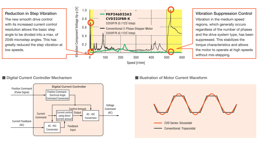
Low Vibration with Full-Time Microstepping
Low vibration and noise reduction have been achieved across all speed ranges by significantly improving the vibration level with the use of a fully digital-controlled full-time microstep driver. The CVD 5 phase driver and motor has further improved vibration characteristic.
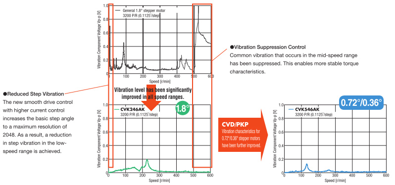
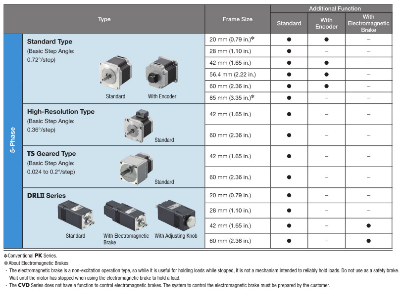
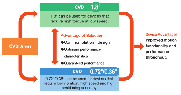
There's a Wide Choice with 1.8° and 0.72°/0.36° Stepper Motors
The size, installation and I/O connectors for the CVD drivers and 1.8° or 0.72°/0.36° motors are the same. Because of this, it is easy to evaluate and select the proper package for the requirement.
Low Vibration Achieved by Full-Time Microstep Drive
The CVD Series is a fully digital control driver. Currents are controlled digitally and calculated by a high-performance CPU. The waveform of the current for each phase is changed from the conventional trapezoidal to sinusoidal, which allows for micro-step driving in all speed regions, and has reduced vibration even more.
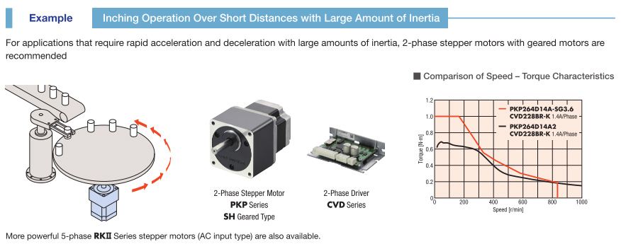
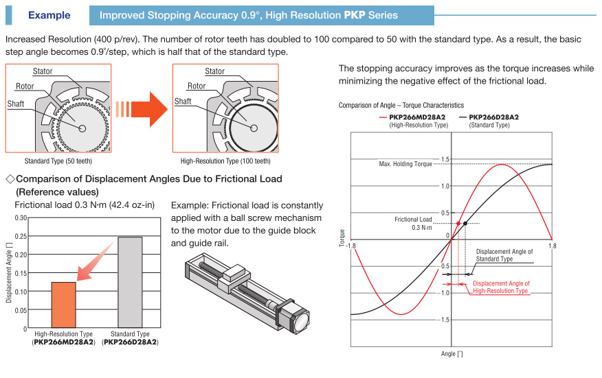
A Motor that Matches the Desired Specifications can be Selected from a Wide Range of Speed and Torque Variations

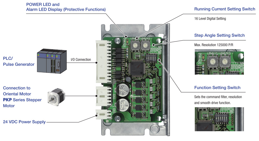
Pulse Input Type Driver
This driver meets the needs for easy synchronized operation with pulse input type drivers.
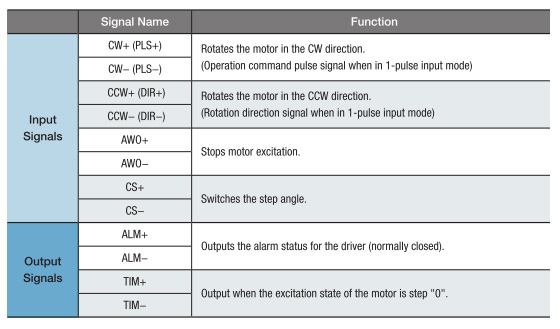
I/O Signals
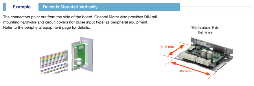
Mounting Options
Different driver shapes and connection methods are available to meet a wide range of mounting locations.


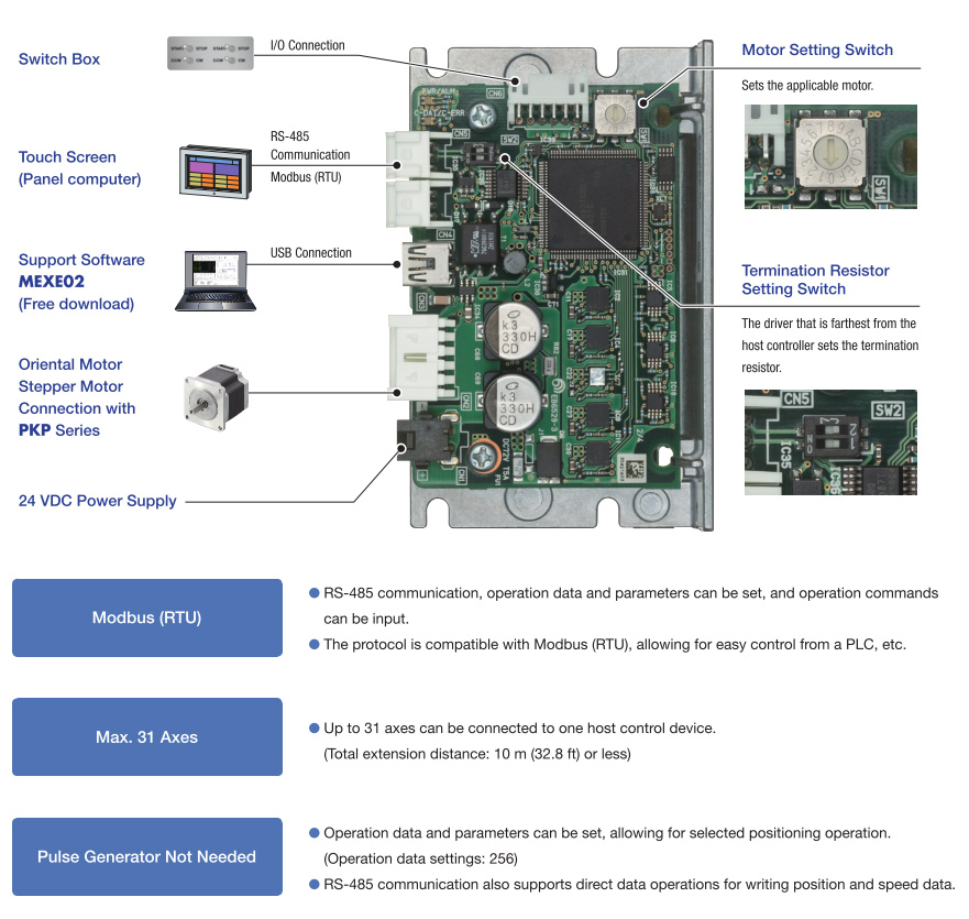
RS-485 Communication Type
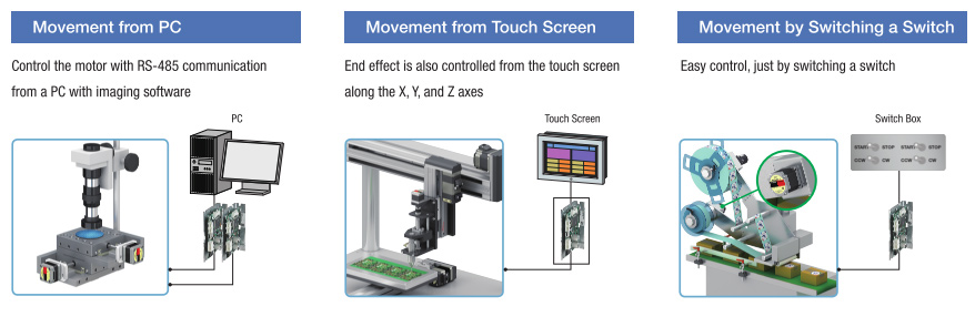
Movement with Modbus (RTU) control? Simple data setting with touch screen? These drivers meet those needs.
Movement Examples
Simple Editing and Setting Operation Data and Parameters
Support Software MEXE02
Basic settings, such as operation data editing and parameter settings, can be easily made from a computer. Sequence control is also possible, making simple system confi guration possible without a host sequence.

Contributes to Visualization
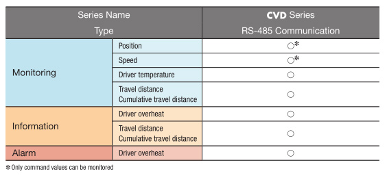
Comes with a monitoring function that contributes to visualization.
Pulse Generator not Needed
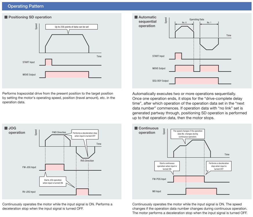
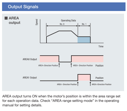
The RS-485 communication type can set operation data in the driver, allowing for operation data to be selected and executed from a host. Operation data can also be linked.
Mounting Options
Different driver shapes and connection methods are available to meet a wide range of mounting locations.


Fully Closed-Loop Stepper Motor Control
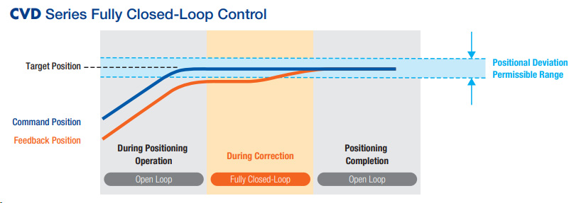
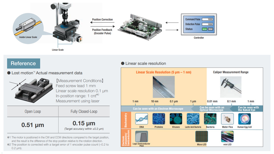
The use of fully closed-loop control, which provides direct feedback for the mechanism position, allows for the correction of any deviations between the command position and the feedback position.
Enables High Precision Positioning
Uses open loop control at the start of positioning to take advantage of the high response of the stepper motor. After the positioning command has been completed, it uses feedback from external sensors to correct the position.
No Gain Adjustment or Hunting with Stepper Motors
No Gain Adjustment Required
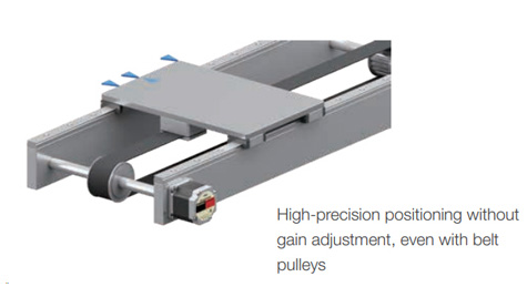
Unlike servo motors, gain adjustment to match the mechanism is not necessary. Since the positioning operation does not use the usual feedback from an encoder, adjustments to mechanisms like belt pulleys, cams, or loads become unnecessary.Holding the Stop Position without Hunting
When positioning is completed, the motor stops with its own holding force without hunting. This is ideal for applications where absence of vibration upon stopping is required.
Supports Various External Sensors to Match the Mechanism
Compatible with various encoders from a variety of manufacturers, allowing for feedback from the encoder best suited to the mechanism to be used.

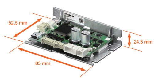
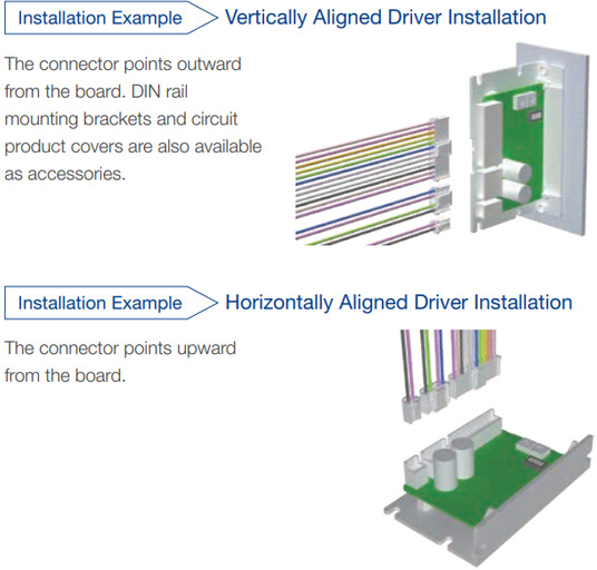
Common Driver Sizes and Installation Method
Drivers with different connector directions are available to match the end user’s driver installation methods.The mounting plate common to the CVD Series is used, with the same mounting hole pitch.
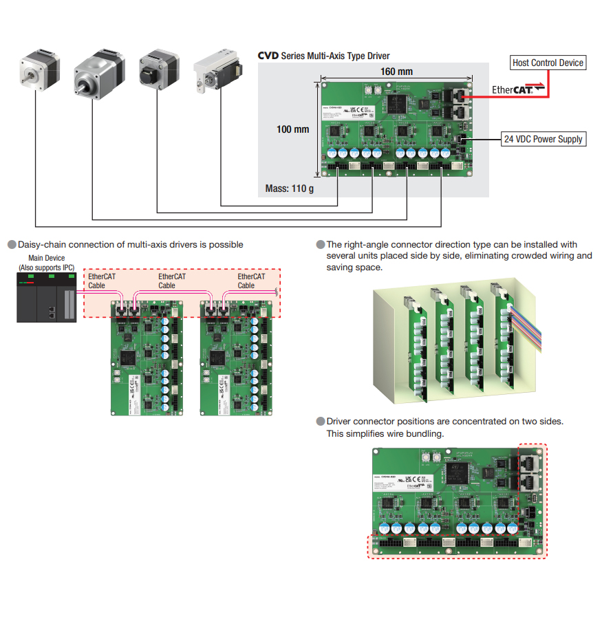
EtherCAT Compatible/4-Axis Control Reduces Wiring and Saves Space
- I/O signals are consolidated into a single EtherCAT communication cable. Wiring for communication, power supply, etc. for 4-axis are integrated into a single driver
- Reduces work hours for wiring and decreases problems from mis-wiring
- Integrated management of device information including motor information by using an EtherCAT master
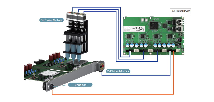
Combined Use of 2-Phase/5-Phase Motors and Synchronous Control is Possible Using EtherCAT Communication
- A single driver can control 2-phase/5-phase motors and actuators, which reduces parts inventory and management costs
- Synchronous control is possible while utilizing the different characteristics of 2-phase/5-phase motors via EtherCAT communication
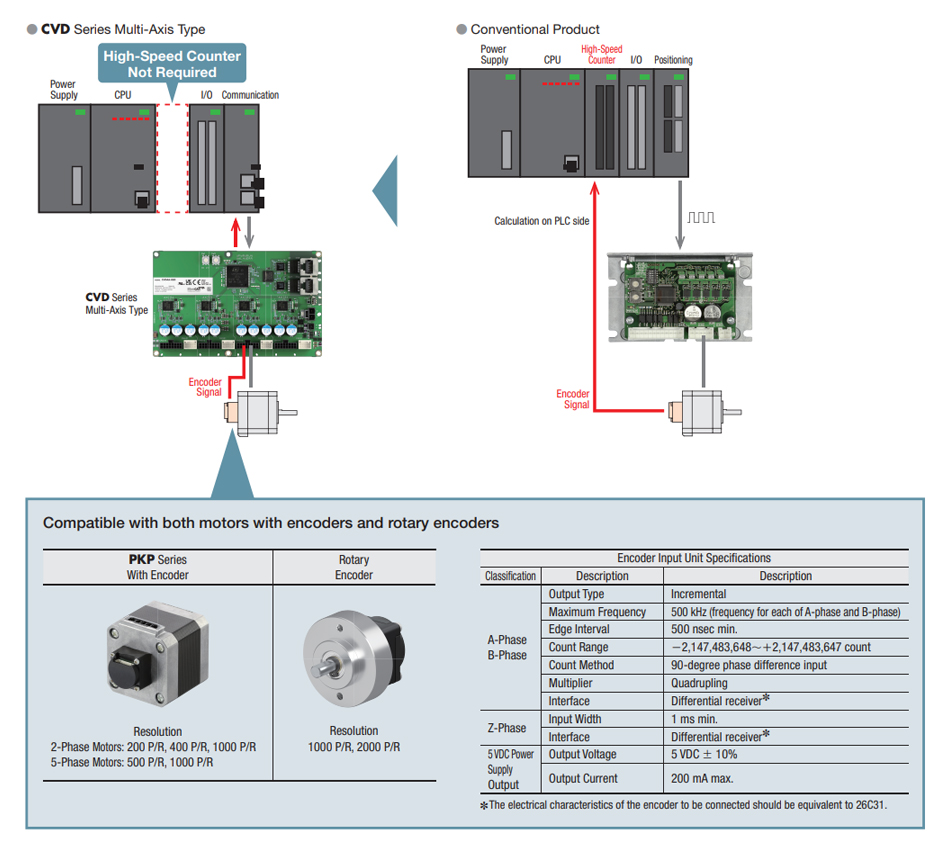
Acquire Encoder Information and Position Deviation Detection
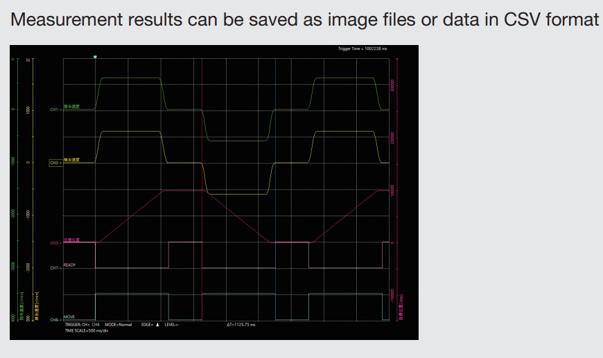
Driver includes a function to acquire encoder information. Position deviation can be detected by the driver and outputs a signal without the need for a host controller. The actual position and speed of the motor can also be monitored on a computer screen by using the support software MEXE02.
- No high-speed counter needed, reducing host controller costs
- Outputs signal to the host controller using EtherCAT communication. Reduces program creation time.
The Encoder Detection Information can be Monitored Using the Support Software MEXE02 (Free)
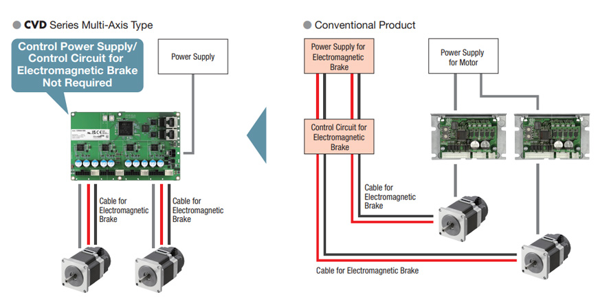
Automatic Control of Electromagnetic Brake and Power Supply
- No electromagnetic brake control circuit is needed, which reduces program creation time
- Reduced wiring work time
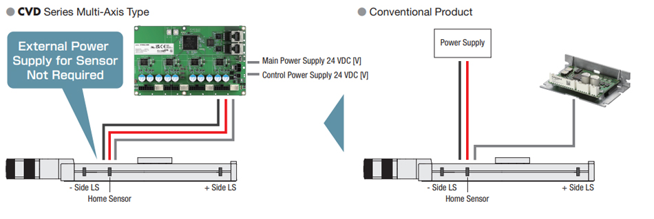
Can Provide Power to Sensors
Other Functions
Alarm Output
- Output of an excessive position deviation alarm allows for detection of motor misstep/stepout (Main circuit overheat alarm, etc. can also be output)
Information
- Output of an excessive position deviation alarm allows for detection of motor misstep/stepout (Main circuit overheat alarm, etc. can also be output)
- Can be monitored using EtherCAT communication
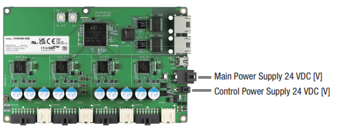
Separation of Main Power and Control Power
- Supports addition of a separate external safety relay to shut off the main power supply
- Can be monitored using EtherCAT communication
- Monitoring, etc. via EtherCAT communication is possible even when the main power supply is shut off
Main Power Supply Inrush Current Suppression Function
- This function protects the circuits in the main power supply unit from inrush currents that occur when the main power supply is turned on.
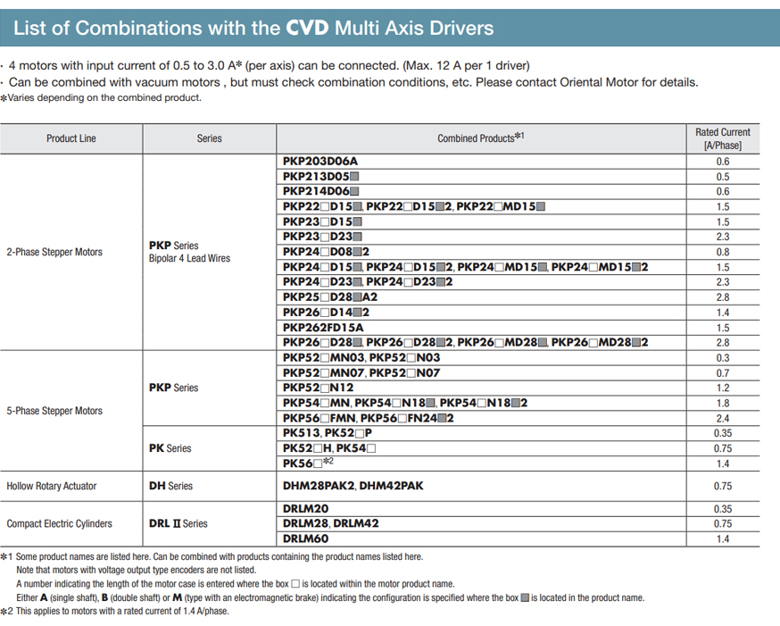
*PKP Series voltage output type encoder motors are not compatible with this driver
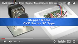
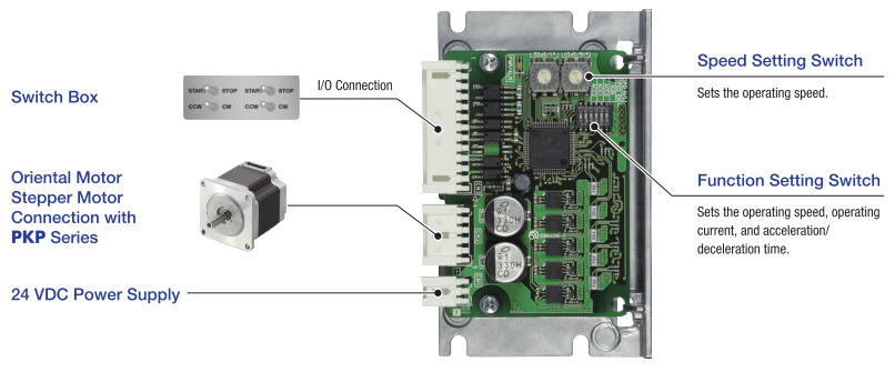
Speed Control Type (CVK-SC)
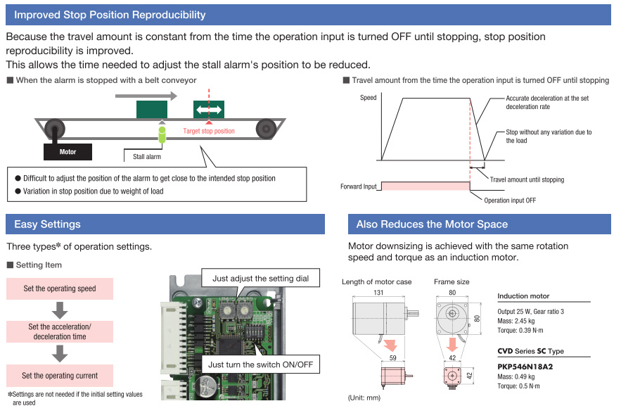
Simple speed control with a stepper motor. Suppression of stop position variation in constant speed motors. These drivers meet those needs.
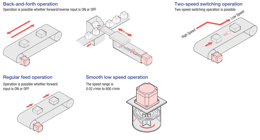
Simple Speed Control
This product continues to rotate at the setting speed while forward (reverse) input is ON, but instantly tops when the input is OFF. Various operations can be achieved from the PLC depending on the length of time the forward (reverse) input is ON.
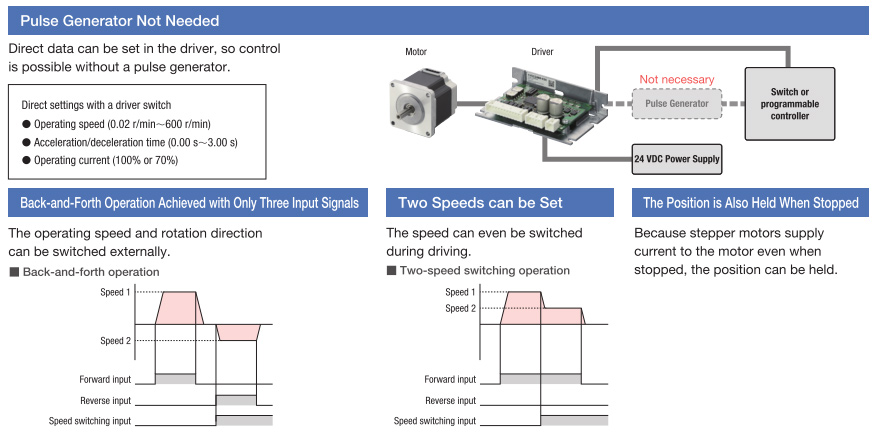
Contributes to Cost Reduction, Simple Control, and Improved Stopping Accuracy in Speed Control
Using Stepper Motors
These motors are the answer to demands like keeping costs down with simple operations, and having a position holding function while stopped.
Using Constant Speed Motors and Inverters
Using a Stepper motor vs other motor types can improve stop position variation and sensor stopping accuracy.
PKP Series 5-Phase Stepper Motors
The PKP series stepper motor offers balanced performance enhanced by high torque, low vibration and low noise.
- 0.72° (500 pulse/rev) & 0.36° (1000 pulse/rev)
- New Pentagon Winding
- Encoders - 500 Lines of Resolution
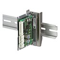
Driver Mounting Bracket
This is a DIN Rail mounting bracket for drivers with installation plates.
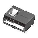
Driver Cover
This cover provides protection for the driver and prevents accidental contact. For use with right-angle type connector type with installation plate.
RS-485 Communication Cables
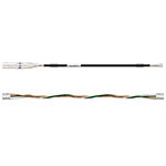
Communication cables for RS-485 type drivers.
Driver to Controller |
|
Driver to Driver |
Encoder Cable
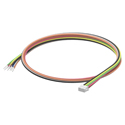
Encoder Cable for CVD Series Fully Closed-Loop Control Driver.
Encoder Output |
|
Encoder Input |
I/O Cable
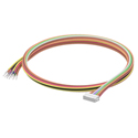
I/O Cable for CVD Series Fully Closed-Loop Control Driver.
Input/Output Signal |
DC Power Supply Cable
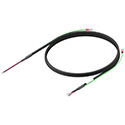
Power Cable for CVD Driver.
0.5 m [1.6 ft] |
|
1 m [3.3 ft] |
|
1.5 m [4.1 ft] |
|
2 m [6.6 ft] |
Driver Cable Set - RS-485 Communication Type
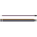
Power supply cable is used to connect the driver and the power supply. I/O signal cable is used to connect the driver and programmable controller.
*Cables required for 15W, 30W and 50W drivers, included with 100W driver
RS-485 Driver |
0.3 m |
|
1 m |
Motor - Driver Connector Cables
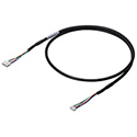
A cable that directly connects a connector-coupled motor and driver. A motor and driver can be directly connected using the connectors on both ends.
Driver Cable Set
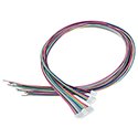
As an accessory for DC input drivers, lead wires with a connector are available. These lead wires allow for easy connection of the motor, power supply and input/output signals. The connection cable set includes three connection cables (for motor, power supply and input/output signals).
Item |
Applicable Drivers |
CVD503, CVD507, CVD512, CVD514, CVD518, CVD524 |
|
CVD528, CVD538 |
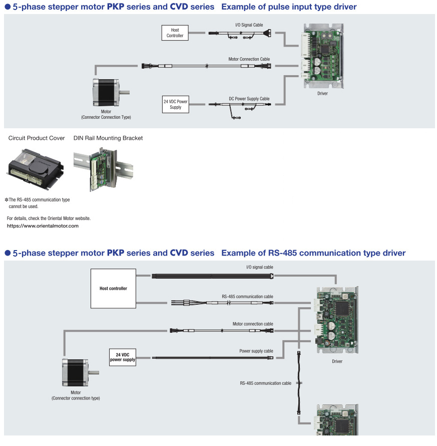
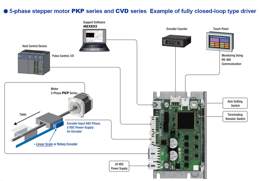
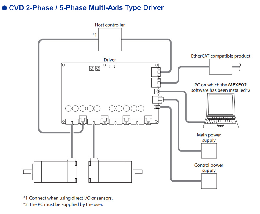
System Configuration
CAD / Manual Search
To locate product CAD and Operator Manuals please search using the product Item Number.


