PKP Series 5-Phase Stepper Motors (DC Input)
PKP Series 5-Phase Stepper Motors (DC Input)
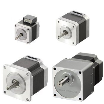
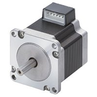
The PKP series 5-phase stepper motor offers balanced performance enhanced by high torque, low vibration and low noise.
- 0.72° (500 pulse/rev) & 0.36° (1000 pulse/rev)
- New Pentagon Winding
- Encoders - 500 or 1000 Lines of Resolution
- 5-Phase Stepper Motor Drivers Available
- Motor Cable sold separately (*required)
Stepper Motor Lineup
Frame Size |
Motor Types |
Available Options |
Current per Phase |
Lead Wires |
Max. Holding Torque |
|
Standard Type (0.72°) |
Encoder | 0.35 ~ 1.2 A |
5 |
5.9 ~ 12.9 oz-in |
0.042 ~ 0.091 N·m |
|
High-Resolution (0.36°) |
||||||
Standard Type (0.72°) |
Encoder |
1.8 A |
5 |
31 ~ 71 oz-in |
0.22 ~ 0.5 N·m |
|
High-Resolution (0.36°) |
||||||
Geared |
- |
5.7 ~ 10.6 lb-in |
0.65 ~ 1.2 N·m |
|||
|
|
Standard Type (0.72°) |
Encoder |
2.4 ~ 3.8 A |
5 |
62 ~ 326 oz-in |
0.44 ~ 2.3 N·m |
High-Resolution (0.36°) |
||||||
Geared |
- |
2.8 A |
15.9 ~ 53 lb-in |
1.8 ~ 6 N·m |
||
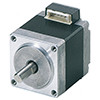
PKP Series Stepper Motors (0.72°)
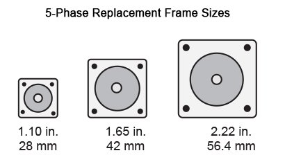
- 1.10 in. (28 mm)
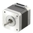
- 1.65 in. (42 mm)
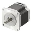
- 2.22 in. / 2.36 in. (56.4 mm / 60 mm)
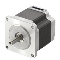
High Accuracy
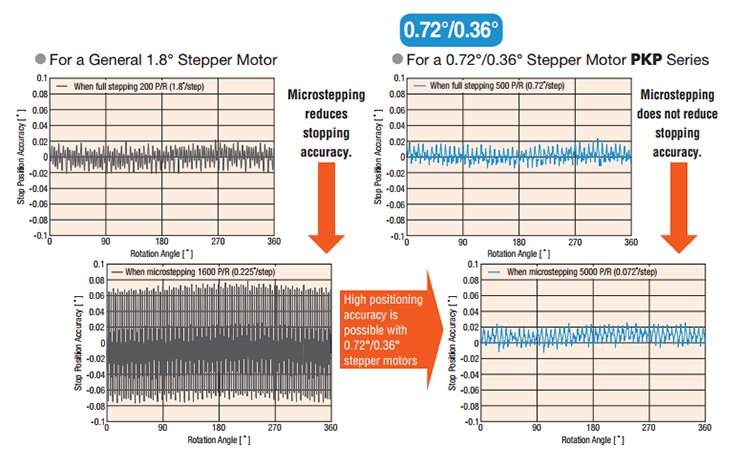
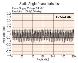
In general, stopping accuracy tends to be lower during microstep operation than full step operation and this effect is more noticeable in a 1.8° motor. In this situation, using a 0.72°/0.36° stepper motor along with a CVD 5-phase driver enables a higher positioning accuracy.
Stopping Accuracy:
- 0.72° = ±0.05° (±3 arcmin)
- 0.36° = ±0.034° (±2 arcmin)
Low Vibration and Low Noise
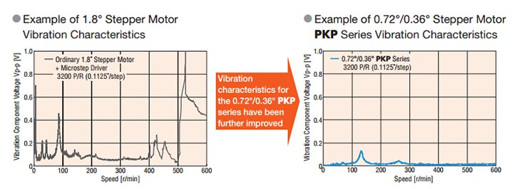
Because the basic step angle is small at 0.72° (0.36° for high-resolution type), the vibrations and noise are lower than the 2-phase stepper motor with a basic step angle of 1.8°. Also, vibrations and noise can be further reduced with the use of a 5-phase stepper motor and CVD 5-phase driver..
Direct Replace for 2-Phase Motors
Our 5-phase stepper motors are now available in multiple frame sizes to allow for direct replacement of standard 2-phase motors allowing for increased resolution and lower vibration on your application.
Utilizing Hybrid Stepper Motor Technology
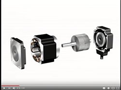
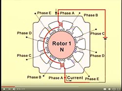
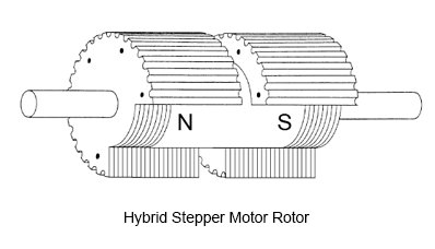
A hybrid stepper motor is a combination of the variable reluctance and permanent magnet type motors. The rotor of a hybrid stepper motor is axially magnetized like a permanent magnet stepper motor, and the stator is electromagnetically energized like a variable reluctance stepper motor. Both the stator and rotor are multi-toothed.
A hybrid stepper motor has an axially magnetized rotor, meaning one end is magnetized as a north pole, and the other end a south pole. Toothed rotor cups are placed on each end of the magnet, and the cups are offset by half of a tooth pitch.
High-Resolution Type Stepper Motors (0.36°)
- 1.10 in. (28 mm)
- 1.65 in. (42 mm)
- 2.36 in. (60 mm)
High-Resolution
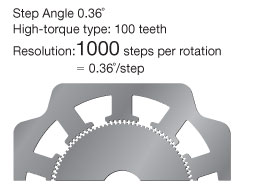
The 0.36° high-torque type stepper motors provide 1000 steps per revolution by having 100 teeth on the rotor. This contributes to the highest resolution and lowest vibration.
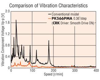
Lowest Vibration
The lowest vibration is achieved using the smallest basic step angle of 0.36°.
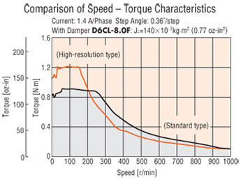
Generates Higher Torque
The high-torque stepper motor generates approx. 1.2 to 1.5 times the torque achieved by the standard motor stepper motor.
Stop Position Accuracy of 2 Arc Minutes (No Load)
The 0.36° high-torque type stepper motor is designed with a stop position accuracy of 2 arc minutes (0.034°) [standard type: 3 arc minutes (0.05°)]. The reduced error helps improve the positioning accuracy.
Spur Gear Stepper Motors (TS)
- 1.65 in. (42 mm)
- 2.36 in. (60 mm)
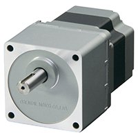
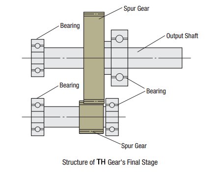
High Speed, Low Backlash Gears
This geared type is made with a simple spur gear design. The torque and speed have been improved.
Because of its high accuracy, this type has the same level of accuracy when compared to our tapered (TH) type without the added cost of tapering.
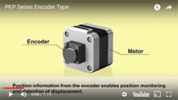
Encoder Equipped Stepper Motors (0.72° or 0.36°)
- 1.10 in. (28 mm)
- 1.65 in. (42 mm)
- 2.22 in. / 2.36 in. (56.4 mm / 60 mm)
Magnetic Encoders
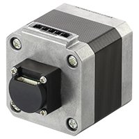
Magnetic encoders do not use a light emitter or a light receiver but still use a code wheel and a sensor. Instead of slits, the code wheel has alternating north and south pole magnets on the outer edge of the code wheel. The magnetic sensor senses changes in magnetic polarity when the poles pass by. The end result is the same as the output circuit outputs pulses to a PLC or HMI. Since there's no need to power the light emitter and receiver, the magnetic encoder uses less power than an optical encoder.
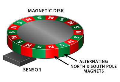
Magnetic encoders are more robust than optical encoders in the sense that they can operate better in humid, dusty, or dirty environments. However, magnetic encoders may not work well in an environment with magnetic interference. Magnetic encoders are also offered in rotary, linear, incremental, and absolute types. To enable a magnetic encoder to track absolute positions, multiple magnetic disks are necessary.
Detecting for Errors
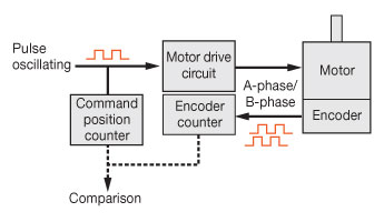
An incremental encoder works by providing an A and B pulse output. The counting is done through external electronics. Here, the encoder counter is compared to the commanded position counter (third party electronics). The point where the counting begins depends on the counter in the external electronics and not on the position of the encoder.
Capable of More Accurate System Control
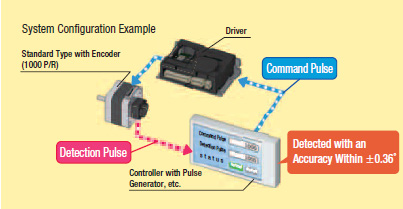
Monitoring the current position and detecting positional errors is possible.
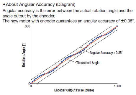
By using a detection pulse guaranteed at ±0.36°, more accurate
system control is possible.
Capable of Highly Reproducible Return-to-Home
The Z-phase signal is output using the excitation home (stable point), so the home sensor (the sensor that detects the home within one rotation, installed on the motor shaft) can be used instead.
It is also easier for the Z-phase output signal and TIM output signal✽ to be used together, increasing the reproducibility of return-to-home.

A rotary encoder is an electro-mechanical device that converts the angular position of a shaft to an analog or digital code. There are two main types: absolute and incremental. Oriental Motor offers incremental types (Line Driver or Voltage (TTL equivalent)) as a standard product for our stepper motors. For an absolute encoder solution, use the AZ Series. For other standard product encoder offerings and motors that correct themselves, contact technical support for assistance.
An incremental encoder provides the incremental change in position of the encoder to the counting electronics. Stepper motors with incremental encoders make it possible to monitor the present position and detect for errors. Position monitoring can be used to detect the position of the motor. For instance, to confirm normal operations, compare commanded position to the actual position.
3-Channel Encoders
Use the Index signal for the return-to-home operation. By using the Index signal, the return-to-home point will be detected with higher accuracy than single use of the return-to-home sensor. The index channel is an optional output channel which provides one pulse per revolution.
Line Driver Output Type
The Line Driver output offers excellent noise resistance because of the differential output and is capable of longer wiring distance compared to the voltage output.
Encoder Specifications
Encoder Code |
R3G |
R3J |
R3GL |
R3JL |
|
Resolution |
500 P/R |
1000 P/R |
500 P/R |
1000 P/R |
|
Angular Accuracy |
±0.36° (Motor output shaft conversion value) |
||||
Output Circuit Type |
Voltage (TTL equivalent) |
Line Driver |
|||
Type |
Incremental |
||||
Output |
A-phase, B-phase, Z-phase (3ch) |
||||
Input Voltage |
5 VDC ±10% |
||||
Input Current |
45 mA or less |
30 mA or less |
|||
CVD 5-Phase Drivers (sold separately)
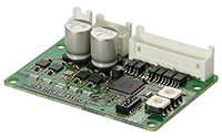
The CVD 5-phase stepper motor driver offers superior performance and value and is ideal for OEM or single axis machines. The CVD stepper motor drivers offer:
- Lowest Vibration and Noise with advanced Microstepping control
- Pulse Input, RS-485 Communications, Fully Closed-Loop or Speed Control Type
- Significantly improves positional accuracy when microstepping
- Small, thin microstepping drive with space saving FETs
- Selectable step angle and microstepping filter control
- Alarms
- 24 VDC Input
- 0.35 ~ 3.8 A/Phase
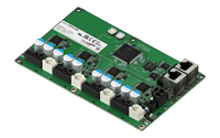
CVD 2-Phase / 5-Phase Multi-Axis Drivers (sold separately)
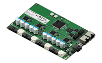
This compact, lightweight 4-axis control CVD driver reduces wiring and saves valuable space. The Multi-Axis Type CVD Series stepper motor drivers offer:
- Wiring for communication, power supply, etc., for the 4-axis, are integrated into a single-driver
- Can be used with 2-phase/5-phase stepper motors
- EtherCAT communication enables synchronous operation
- Automatically controls electromagnetic brakes using data acquired from integrated encoders, which can reduce host controller costs and program creation time
- 2 connector types options
- Alarms
- 24 VDC Input / 0.3 ~ 2.8 A/Phase
![]()
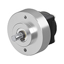
Rotary Encoders
Small, thin, and lightweight stand-alone rotary encoders with an outer diameter of ϕ30 mm can be installed in tight spaces.
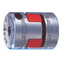
Flexible Couplings
Flexible couplings provide simple connection to drive shaft and reduce vibration and backlash from the motor.
Motor Cables (*required)
This lead wire connection cable with a conveniently crimped connector is for connector-coupled motor, and for connecting motors and drivers.
Encoder cables required for encoder type motors.
Motor - Driver Connector Cables
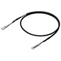
A cable that directly connects a connector-coupled motor and driver. A motor and driver can be directly connected using the connectors on both ends.
Stepper Motor Linear Actuator Attachment
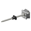
Stepper Motor Linear Actuator Attachment is a linear motion mechanism with a lead screw and resin nut. It saves space and reduces design time compared to a custom-built mechanism. To use with 2-Phase and 5-Phase stepper motors PKP Series frame size 42mm (Round Shaft Type only).
Mounting Brackets
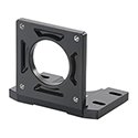
Mounting brackets are convenient for installation and securing a stepper motor or geared stepper motor.
Clean Dampers
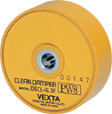
Mechanical dampers suppress stepper motor vibration and improve high-speed performance. An inertia body and silicon gel are hermetically sealed in a plastic case.
(For use with Double Shaft motors)
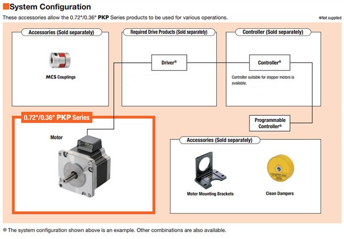
System Configuration
PKP523N12A PKP523N12B PKP525N12A PKP525N12B PKP543N18A2 PKP543N18A2-R2G PKP543N18A2-R2GL PKP543N18A2-TS20 PKP543N18A2-TS30 PKP543N18B2 PKP543N18B2-TS20 PKP543N18B2-TS30 PKP544MN18A PKP544MN18B PKP544N18A2 PKP544N18A2-R2G PKP544N18A2-R2GL PKP544N18A2-TS10 PKP544N18A2-TS3.6 PKP544N18A2-TS7.2 PKP544N18B2 PKP544N18B2-TS10 PKP544N18B2-TS3.6 PKP544N18B2-TS7.2 PKP545N18A2 PKP545N18A2-R2G PKP545N18A2-R2GL PKP545N18B2 PKP546MN18A PKP546MN18B PKP546N18A2 PKP546N18A2-R2G PKP546N18A2-R2GL PKP546N18B2 PKP564FMN24A PKP564FMN24B PKP564FN24A2 PKP564FN24A2-R2G PKP564FN24A2-R2GL PKP564FN24B2 PKP564FN38A2 PKP564FN38A2-R2G PKP564FN38A2-R2GL PKP564FN38B2 PKP564N28A2-R2G PKP564N28A2-R2GL PKP564N28A2-TS20 PKP564N28A2-TS30 PKP564N28AA2 PKP564N28B2-TS20 PKP564N28B2-TS30 PKP564N28BA2 PKP566FMN24A PKP566FMN24B PKP566FN24A2 PKP566FN24A2-R2G PKP566FN24A2-R2GL PKP566FN24B2 PKP566FN38A2 PKP566FN38A2-R2G PKP566FN38A2-R2GL PKP566FN38B2 PKP566N28A2-R2G PKP566N28A2-R2GL PKP566N28A2-TS10 PKP566N28A2-TS3.6 PKP566N28A2-TS7.2 PKP566N28AA2 PKP566N28B2-TS10 PKP566N28B2-TS3.6 PKP566N28B2-TS7.2 PKP566N28BA2 PKP568N28A2-R2G PKP568N28A2-R2GL PKP568N28AA2 PKP568N28BA2 PKP569FMN24A PKP569FMN24B PKP569FN24A2 PKP569FN24A2-R2G PKP569FN24A2-R2GL PKP569FN24B2 PKP569FN38A2 PKP569FN38A2-R2G PKP569FN38A2-R2GL PKP569FN38B2
CAD / Manual Search
To locate product CAD and Operator Manuals please search using the product Item Number.
